 |
|||
|
|
|||
|
Page Title:
REMOVAL OF HANDLE PUSHBUTTON SWITCH |
|
||
| ||||||||||
|
|
 TM 10-3930-660-24-2
ELECTRIC JOYSTICK MAINTENANCE - CONTINUED
0235 00
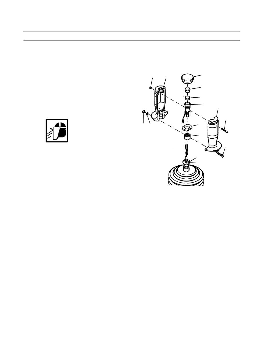
REMOVAL OF HANDLE PUSHBUTTON SWITCH
1.
Pull off boot (8) from handle sections (7).
2.
Remove two screws (9) and two nuts (10) at top of handle sections (7).
3.
Remove two screws (11), two bowed washers (12) and
8
10
7
two nuts (13) at bottom of handle sections (7). Discard
bowed washers.
15
4.
Separate handle sections (7) and remove them from
shaft coupling (14).
19
5.
Remove actuating button (15).
16
7
6.
Remove pushbutton switch (16), nut (17) and flange
(18) as a unit from handle sections (7).
9
18
13 12
17
WARNING
11
Eye protection must be worn when perform-
ing maintenance where components or parti-
14
cles could fly out during procedure. Failure
20
to take precautions could cause injury to per-
sonnel.
Some components are under spring tension.
Wear eye protection and use caution when
409-1127
disassembling them, to avoid injury.
7.
Carefully unsolder all leads from pushbutton switch (16).
8.
Remove nut (17) and flange (18) from pushbutton switch (16).
9.
Remove cover (19) from pushbutton switch (16).
INSPECTION
1.
Check for loose or disconnected plugs at switches (1 thru 4).
2.
Check all switches for loose mounting hardware or visible damage.
INSTALLATION OF HANDLE PUSHBUTTON SWITCH
1.
Assemble parts (17 thru 19) and solder four leads to pushbutton switch (16).
2.
Install cover (19) to pushbutton switch.
3.
Install flange (18) and nut (17) to pushbutton switch (16).
NOTE
Pin numbers are printed on body of pushbutton switch.
4.
Solder green electrical lead of joystick to pin 1 of pushbutton switch (16).
5.
Solder yellow electrical lead of joystick to pin 2 of pushbutton switch (16).
6.
Solder green jumper lead to pin 1 and pin 3 of pushbutton switch (16).
0235 00-2
|
|
Privacy Statement - Press Release - Copyright Information. - Contact Us |
