 |
|||
|
|
|||
|
|
|||
| ||||||||||
|
|
 TM 10-3930-660-24-1
BOOM HOIST CYLINDERS REPLACEMENT - CONTINUED
0201 00
REMOVAL - CONTINUED
10.
Using boom hoist joystick control valve, fully retract cylinder (2).
11.
Stop engine (TM 10-3930-660-10).
WARNING
Use caution when handling heavy parts. Provide adequate support and use assistance during procedure.
Ensure that any lifting device used is in good condition and of suitable load capacity. Keep clear of heavy
parts supported only by lifting device. Failure to follow this warning may cause injury or death.
NOTE
Weight of each boom hoist cylinder is approximately 182 lb (83 kg).
12.
Carefully lower cylinder (2), using lifting device, until cylinder (2) is resting on board placed on main deck.
CAUTION
Wipe the area clean around all hydraulic connections to be opened during removal. Cap lines and plug open-
ings after removing lines. Contamination of the hydraulic system could result in premature failure.
NOTE
If more than one hydraulic line is to be removed, identify lines to assure proper installation. Use suitable
container to catch any hydraulic oil that may drain from system.
13.
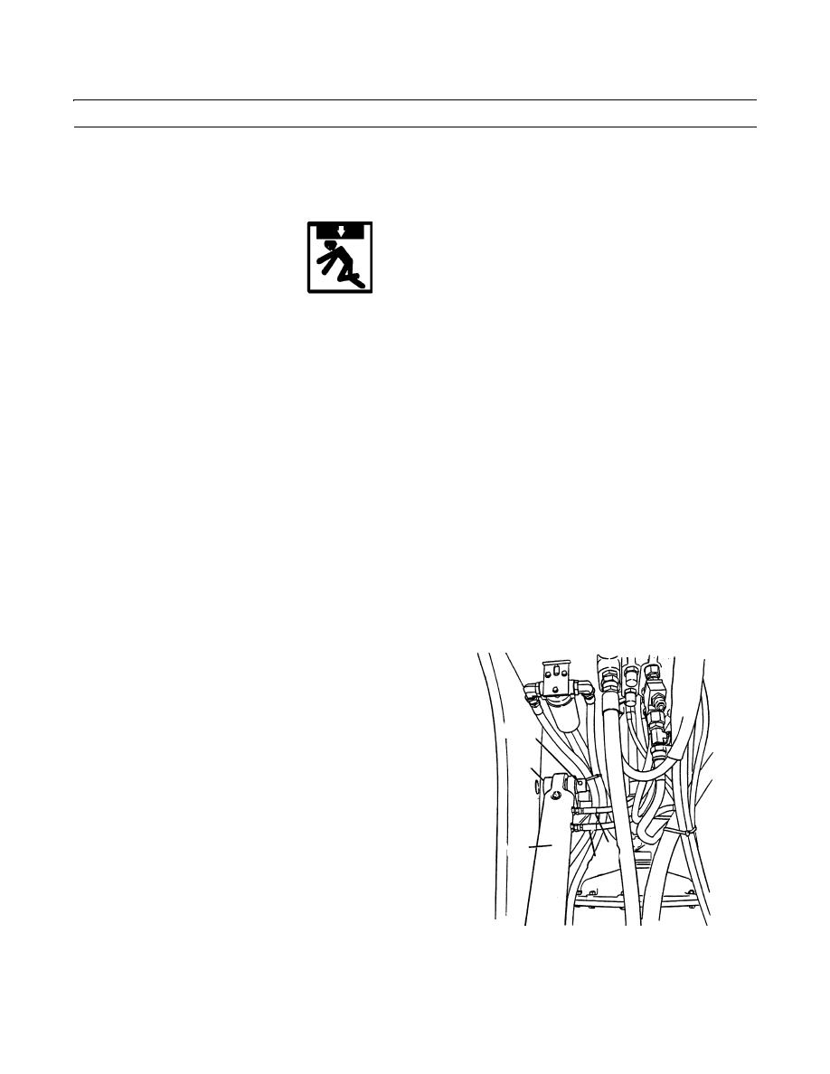
Disconnect hydraulic lines (5 and 6) from cylinder ports.
14.
To remove boom hoist cylinder lower pivot pin (7), remove locknut (8) and screw (9). Discard locknut.
15.
Remove lower pivot pin (7) using pin puller.
16.
Move lifting device to cylinder balance point and carefully lift cylinder (2) off vehicle.
INSTALLATION
NOTE
Remove caps and plugs as hoses are
installed. Wipe all sealing surfaces on cyl-
8,9
inder and hoses clean and dry.
7
1.
Carefully lower cylinder (2) onto board placed on
main deck using lifting device.
NOTE
Apply antiseize compound to lower pivot
pin as installed.
2
6
2.
Align cylinder base lower mounting holes and install
5
lower pivot pin (7), screw (9) and new locknut (8).
3.
Connect hydraulic lines (5 and 6) as tagged during
cylinder (2) removal.
409-792
4.
Carefully raise cylinder (2) using lifting device until
rod eye of cylinder (2) is aimed at pivot pin mounting
hole on boom.
0201 00-3
|
|
Privacy Statement - Press Release - Copyright Information. - Contact Us |
