 |
|||
|
|
|||
|
|
|||
| ||||||||||
|
|
 TM 10-3930-660-24-1
FORK SIDESHIFT CYLINDERS REPLACEMENT - CONTINUED
0200 00
INSTALLATION - CONTINUED
9.
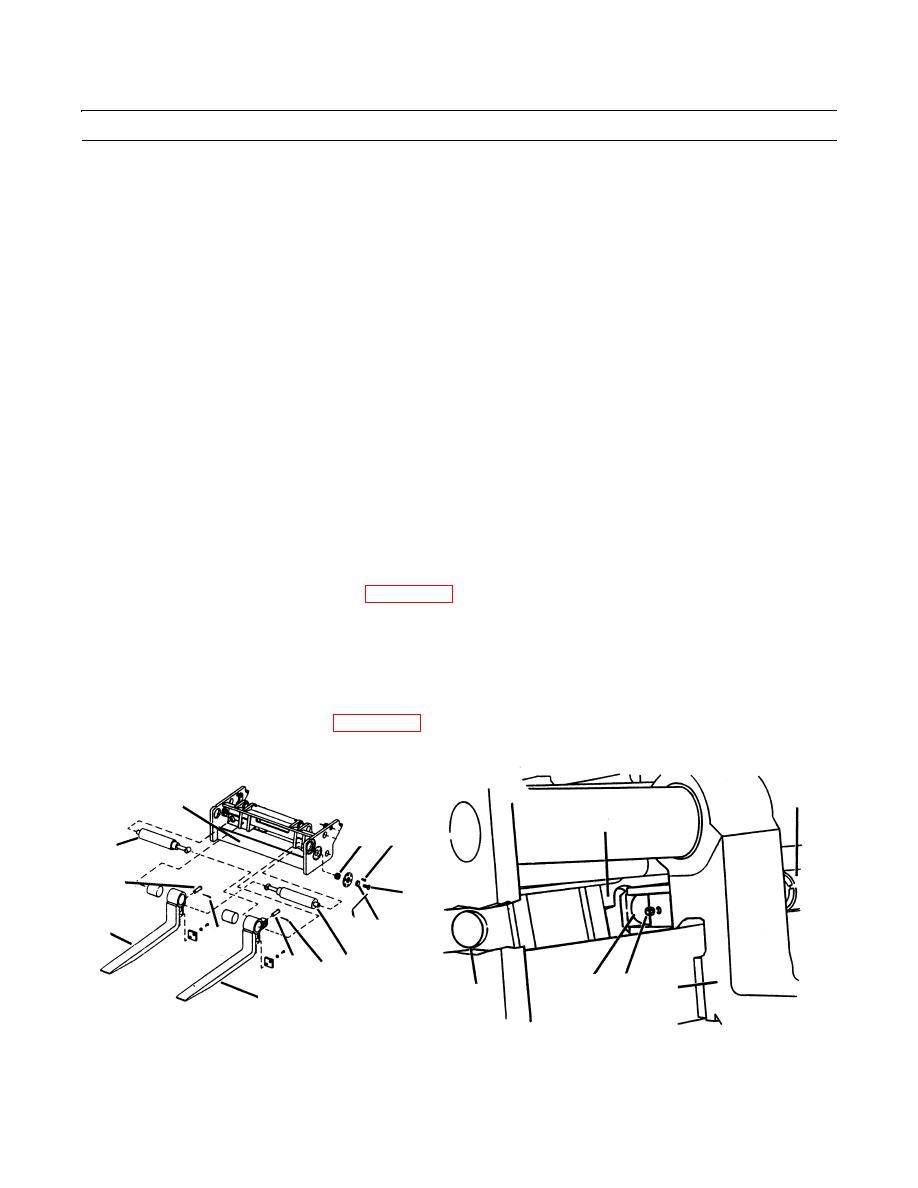
Align left fork (2) with left notch in fork carriage (3).
10.
Extend left fork sideshift cylinder (11) until it aligns with left fork (2) (TM 10-3930-660-10).
11.
Install pin (13) in left fork sideshift cylinder (11).
12.
Install new cotter pin (12) in right side of pin (13).
13.
Place right fork sideshift cylinder (1) in fork carriage (3).
14.
Apply loctite to threads of socket head screw (9).
15.
Install socket head screw (9) and retainer (10) in left side of fork carriage (3). Torque socket head screw to 46 lb-ft (62
Nm).
16.
Install two hydraulic lines (8) on right fork sideshift cylinder (1) as tagged.
17.
Shift left fork (2) to left side of fork carriage (3).
18.
Align pin (5) hole in right fork (6) with access hole (7) in fork carriage (3).
19.
Extend right forks sideshift cylinder (1) until it aligns with access hole (7) in fork carriage end pin (5) hole in right fork
(6).
20.
Install pin (5) in right fork sideshift cylinder (1).
21.
Install new cotter pin (4) in left side of pin (5).
22.
Install fork auto leveler switch and cover (WP 0080 00).
23.
Start engine (TM 10-3930-660-10).
24.
Operate fork sideshift function and sideshift forks five times. Check for proper operation and leaks (TM 10-3930-660-
10).
25.
Stop engine and relieve hydraulic pressure by operating frame tilt controls (TM 10-3930-660-10).
26.
If necessary, bleed hydraulic pumps (WP 0172 00).
1
3
3
15
16
11
5
9
6
17 10
4
13
12 1
5
7
6
7
2
409-784
409-787
END OF WORK PACKAGE
0200 00-4
|
|
Privacy Statement - Press Release - Copyright Information. - Contact Us |