 |
|||
|
|
|||
|
|
|||
| ||||||||||
|
|
 TM 10-3930-660-24-1
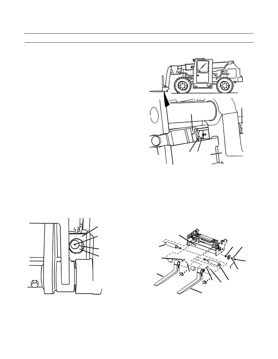
FORK SIDESHIFT CYLINDERS REPLACEMENT - CONTINUED
0200 00
REMOVAL
1.
To remove right fork sideshift cylinder (1), shift left
fork (2) to left side of fork carriage (3), (TM 10-3930-
660-10).
2.
Remove cotter pin (4) from right fork sideshift cylin-
der (1). Discard cotter pin.
3.
With assistance, align pin (5) in right fork (6) with
access hole (7) in fork carriage.
1
4.
Use a slide hammer to remove pin (5) through access
hole (7).
3
NOTE
The thread size of hole in end of pin is 1/4-
20.
5.
Operate controls to shift right fork (6) to left side of
fork carriage (3). The right fork will not move, but
right fork sideshift cylinder (1) will be fully retracted.
6
5
7
7
NOTE
409-782
Tag hydraulic lines to aid in installation.
6.
Disconnect two hydraulic lines (8) from right fork sideshift cylinder (1). Plug and/or cap all hydraulic fittings.
7.
Remove socket head screw (9) and retainer (10) from left side of fork carriage (3).
8.
Lift right fork sideshift cylinder (1) from fork carriage (3).
9.
To remove left fork sideshift cylinder (11) align left fork (2) with left notch in fork carriage (3).
10.
Remove cotter pin (12) and pin (13) from left fork sideshift cylinder (11). Discard cotter pin.
FORK CARRIAGE
THREAD SIZE
3
1/4-20
15
16
11
5
5
6
9
6
17 10
4
13
12 1
2
409-783
RIGHT SIDE VIEW OF FORK CARRIAGE
409-784
0200 00-2
|
|
Privacy Statement - Press Release - Copyright Information. - Contact Us |
