 |
|||
|
|
|||
|
|
|||
| ||||||||||
|
|
 TM 10-3930-660-24-1
TIRES REPLACEMENT - CONTINUED
0135 00
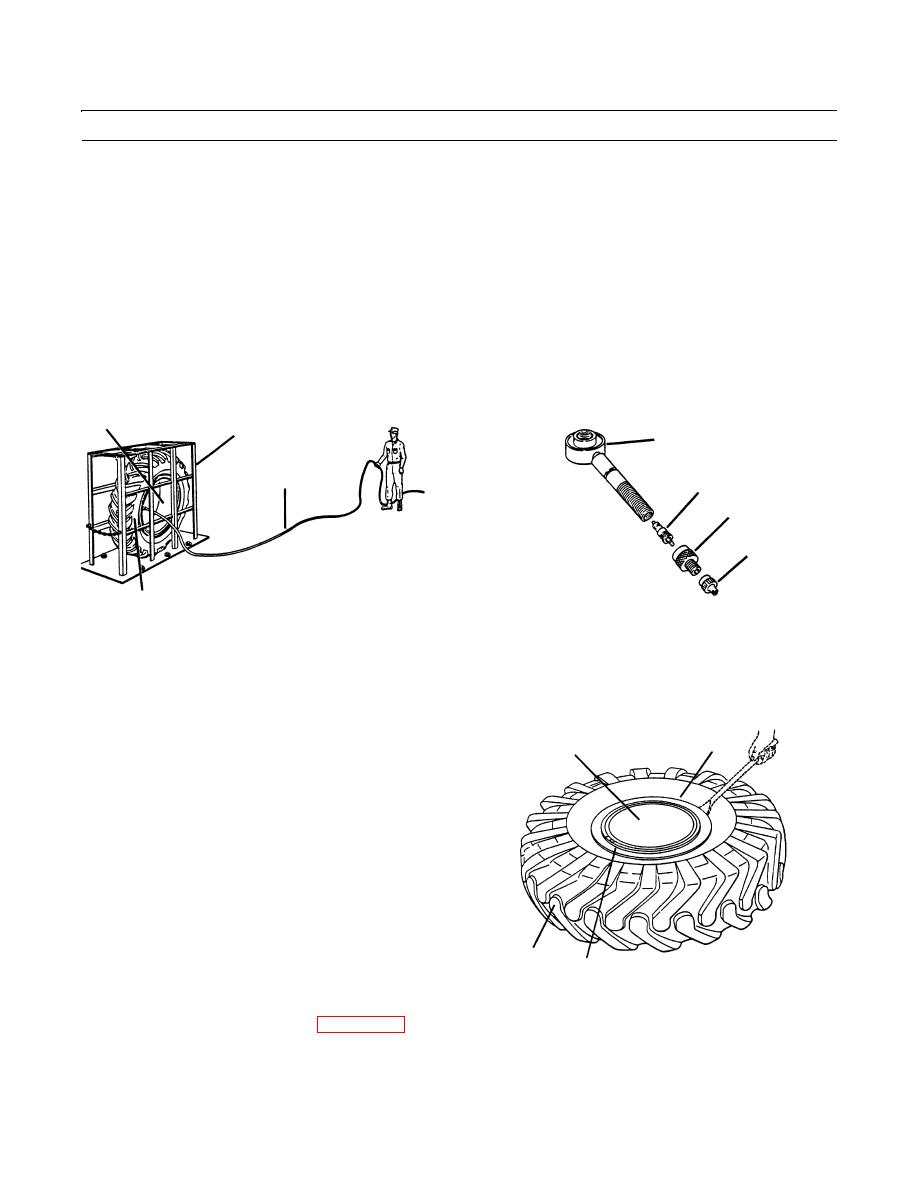
MOUNTING - CONTINUED
15.
Place wheel assembly (6) and tire (3) in inflation safety cage (G).
16.
Remove cap (4) from adapter (5).
17.
Using an airhose and gauge (H) for safety cage use, inflate tire (3) enough to seat both tire beads. Tire beads should seat
before reaching maximum tire pressure of 45 psi (310 kPa).
18.
Remove airhose and allow tire to completely deflate. Visually inspect tire beads, aligning ring (7) and lock ring (8) to
see that they are properly seated.
19.
Install valve core (1) to valve stem (2) and inflate tire (3) to proper pressure.
20.
Remove adapter (5) from valve stem (2).
21.
Install valve core (1) into valve stem (2) with valve core extractor.
6
G
2
H
1
5
4
3
409-533
409-532
NOTE
Inflate tires for front axle to 45 psi (310 kPa). Inflate tires for rear axle to 40 psi (276 kPa).
22.
Inflate tire (3) to normal operating pressure and visu-
7
6
ally inspect tire beads, aligning ring (7) and lock ring
(8) to see that they are properly seated.
23.
Install cap (4) onto adapter (5) finger-tight and remove
wheel assembly (6) from inflation safety cage (G).
3
8
409-534
24.
Install wheel assembly to vehicle (WP 0134 00).
END OF WORK PACKAGE
0135 00-6
|
|
Privacy Statement - Press Release - Copyright Information. - Contact Us |
