 |
|||
|
|
|||
|
|
|||
| ||||||||||
|
|
 TM 10-3930-660-24-1
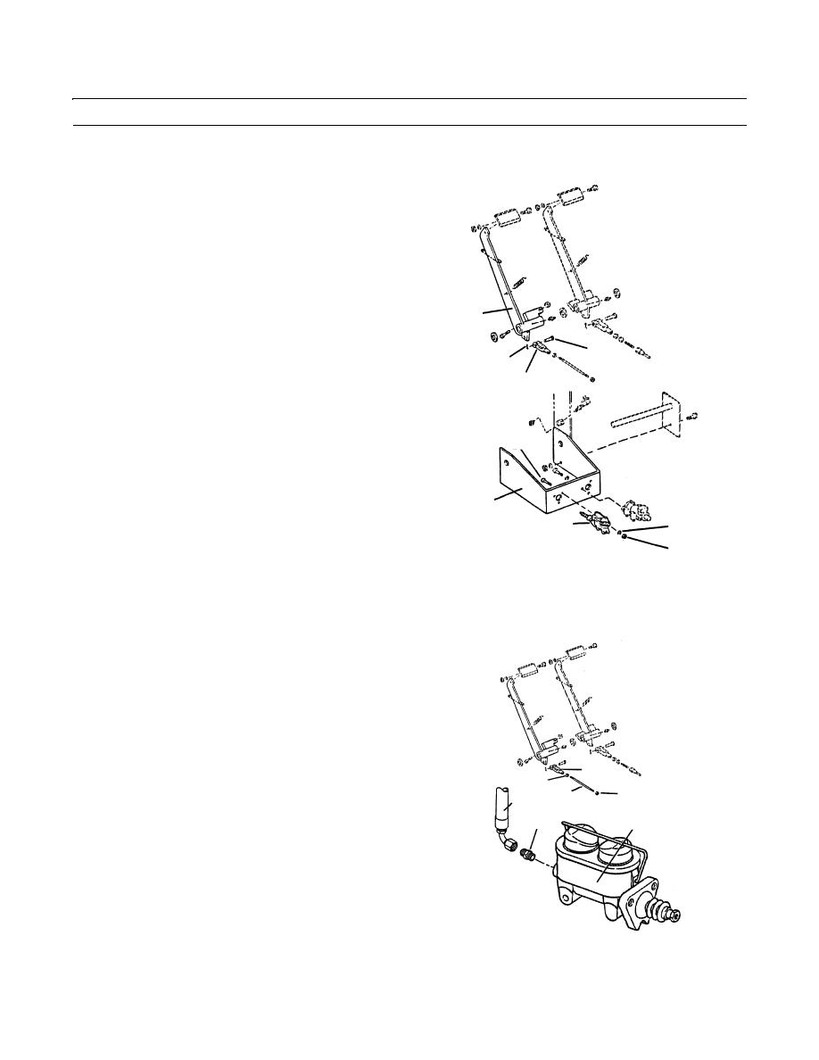
TRANSMISSION DISCONNECT MASTER CYLINDER ASSEMBLY REPLACEMENT - CONTINUED
0117 00
REMOVAL - CONTINUED
2.
Remove cotter pin (4) and clevis pin (5) securing cle-
vis (6) to pedal arm (7). Discard cotter pin.
3.
Remove three nuts (8), lockwashers (9) and capscrews
(10), securing master cylinder assembly (3) to bracket
(11). Remove master cylinder assembly (3) from vehi-
cle. Discard lockwashers.
4.
Remove linkage from master cylinder assembly (3).
7
5.
Loosen jamnut (12) on pushrod pin (13). Remove cle-
vis (6) and jamnut (12) from pushrod pin (13).
5
6.
Loosen jamnut (14) on pushrod pin (13). Remove
4
pushrod pin (13) from master cylinder assembly (3).
6
Remove jamnut (14) from pushrod pin (13).
10
11
9
3
8
409-460
INSTALLATION
NOTE
Do not tighten parts (6, 12, 13 or 14) at
this time.
1.
Install jamnut (14) on pushrod pin (13). Install push-
rod pin (13) to master cylinder assembly (3).
6
2.
Install jamnut (12) and clevis (6) on pushrod pin (13).
12
14
1
13
3.
Position master cylinder assembly (3) on bracket (11)
2
3
and secure with three nuts (8), three new lockwashers
(9) and three capscrews (10).
4.
Remove plugs from holes on hose (1) and master cyl-
inder assembly (3). Connect hydraulic hose and
adapter (2) to master cylinder assembly.
5.
Check oil level of master cylinder assembly and add
409-462
oil as required.
0117 00-2
|
|
Privacy Statement - Press Release - Copyright Information. - Contact Us |
