 |
|||
|
|
|||
|
|
|||
| ||||||||||
|
|
 TM 10-3930-660-24-1
HYDRAULIC BYPASS SWITCH MAINTENANCE - CONTINUED
0091 00
TESTING - CONTINUED
WARNING
This machine must be operated only by authorized personnel who have satisfactorily completed a program
of training which must include familiarity with safe operating procedures, characteristics and a knowledge
of applicable codes, regulations and facilities directives. Untrained personnel subject themselves and others
to the possibility of injury or death from the improper operation of this machine. Understand the equipment,
its function and the controls before operation.
NOTE
To hear the emergency steering pump while the engine is running it may be necessary to go under the vehi-
cle during step 6.
6.
Have assistant start engine (TM 10-3930-660-10). Check that emergency steering pump stops running shortly after
engine is started.
NOTE
Leave engine start switch in RUN position during step 7.
7.
Place auxiliary fuel shut-off switch in the OFF position (TM 10-3930-660-10). Check that emergency steering pump
starts running after engine stops.
8.
Place starter switch in the OFF position (TM 10-3930-660-10).
9.
Place auxiliary fuel shut-off switch in the ON position (TM 10-3930-660-10).
10.
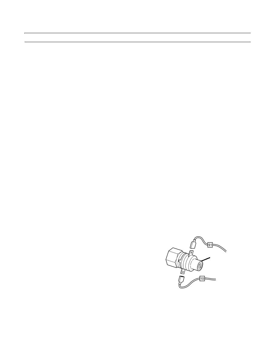
Perform voltage tests on hydraulic bypass switch (1).
NOTE
Leave electrical leads 10 and 91 connected
to switch during steps 11 thru 18.
11.
Attach positive lead of voltmeter to terminal 91 of
1
switch (1).
12.
Attach negative lead of voltmeter to suitable ground.
13.
Place starter switch in RUN position but do not start
the engine (TM 10-3930-660-10).
14.
Voltmeter should indicate approximately 24 volts.
15.
Start engine (TM 10-3930-660-10).
409-3014
16.
Voltmeter should indicate approximately 0 volts.
17.
Stop engine (TM 10-3930-660-10).
18.
Remove voltmeter leads.
0091 00-4
|
|
Privacy Statement - Press Release - Copyright Information. - Contact Us |
