 |
|||
|
|
|||
|
|
|||
| ||||||||||
|
|
 TM 10-3930-660-24-1
FORK AUTO LEVELER SWITCH MAINTENANCE - CONTINUED
0080 00
REMOVAL - CONTINUED
10.
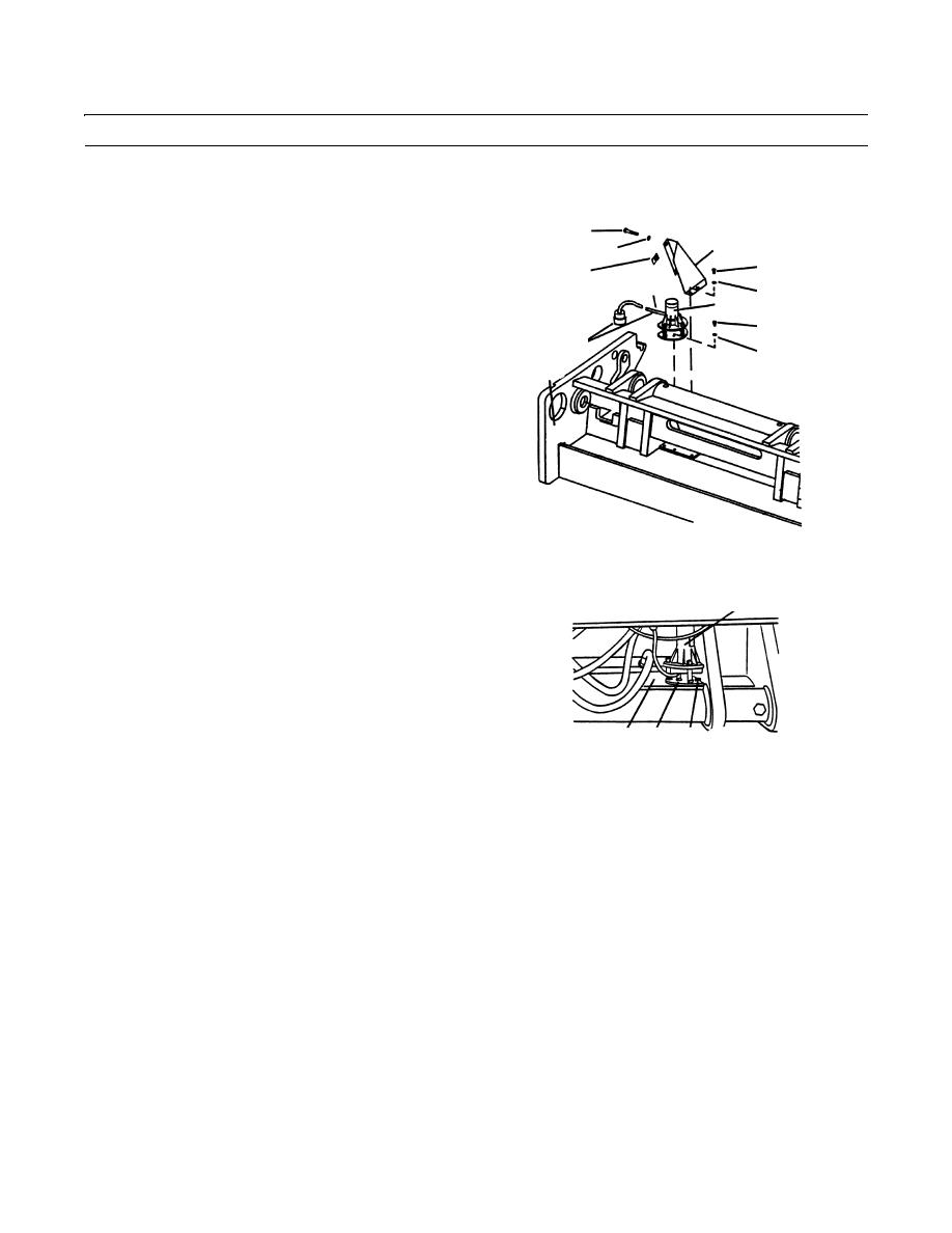
Remove two bolts (24) and two lockwashers (25) from
24
switch cover (26). Discard lockwashers. If necessary,
26
25
remove two retainer nuts (27) from switch cover.
28
27
11.
Remove two capscrews (28) and two lockwashers (29)
30,31
29
from switch cover (26). Remove switch cover from
1
carriage assembly (3). Discard lockwashers.
32
12.
Carefully remove auto leveler switch cable (4) and
4
33
grommet (30) from notch in switch cover (26). If nec-
3
essary, remove conduit (31) from auto leveler cable.
409-304
409-304
13.
Remove four capscrews (32) and four lockwashers
1
(33) securing switch (1) to carriage assembly (3).
Remove switch from carriage assembly. Discard lock-
washers.
3
1 32,33
409-305
INSTALLATION
WARNING
Failure to route auto leveler cable as described may result in damage to vehicle or its load due to malfunc-
tioning of auto leveler system.
NOTE
Auto leveler cable is part of auto leveler switch and is nonrepairable. If auto leveler cable is damaged, entire
auto leveler switch must also be replaced.
Apply loctite to all capscrews and bolts as they are installed.
1.
Install fork auto leveler switch (1) and cable to carriage assembly (3).
2.
Start engine. Position carriage assembly (3) in a down position so that carriage tilt cylinders are fully extended. Stop
engine (TM 10-3930-660-10).
3.
Position switch (1) on carriage assembly (3) and secure with four new lockwashers (33) and three capscrews (32).
0080 00-4
|
|
Privacy Statement - Press Release - Copyright Information. - Contact Us |