 |
|||
|
|
|||
|
Page Title:
LOCATION AND DESCRIPTION OF MAJOR COMPONENTS - CONTINUED |
|
||
| ||||||||||
|
|
 TM 10-3930-660-24-1
EQUIPMENT DESCRIPTION AND DATA - CONTINUED
0002 00
LOCATION AND DESCRIPTION OF MAJOR COMPONENTS - CONTINUED
14
13
12
11
15
10
9
409-002
16
17
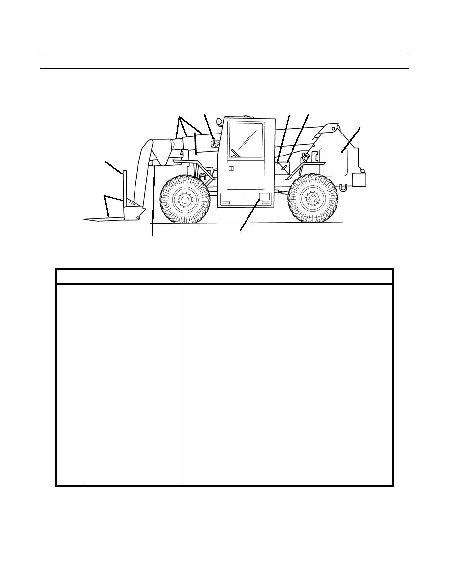
KEY
COMPONENT
DESCRIPTION
9
Forks and Carriage
Serve as an anchoring point of the forks. The fork carriage is also
equipped with automatic fork leveling. Moving a switch will keep the
forks level when raising or lowering the boom.
10
Load Backrest (Shown in fork
Serves as a backstop or support for materials being carried on the forks.
carriage position)
11
Boom
The telescopic, three-stage boom is constructed of welded high
strength steel. The boom will retract or extend the reach and height of
the forks.
12
Boom Angle Indicator
Shows the angle of the boom relative to the horizon.
13
NATO Slave Receptacle
Connection point for starting a disabled vehicle or for receiving
starting assistance when disabled.
14
Battery Box
Holds the batteries which provide current for the electric system.
15
Engine
Provides the necessary power to drive the transmission. The engine
also contains sending units for the Simplified Test Equipment for
Internal Combustion Engines (STE/ICE-R) diagnostics.
16
Tool Box
Storage area for tools and basic issue items.
17
Attachment Hoist Cylinder
Moves the attachment forward and back.
0002 00-3
|
|
Privacy Statement - Press Release - Copyright Information. - Contact Us |