 |
|||
|
|
|||
|
Page Title:
LOCATION AND DESCRIPTION OF MAJOR COMPONENTS |
|
||
| ||||||||||
|
|
 TM 10-3930-660-24-1
EQUIPMENT DESCRIPTION AND DATA - CONTINUED
0002 00
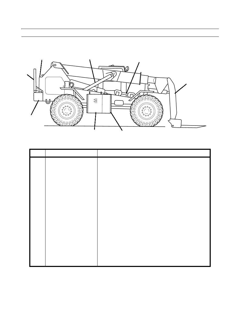
LOCATION AND DESCRIPTION OF MAJOR COMPONENTS
0002 00
1
2
3
8
4
7
6
5
409-001
KEY
COMPONENT
DESCRIPTION
1
Radiator
Contains coolant which provides engine cooling.
2
Boom Hoist Cylinder
Raises and lowers the boom.
The stop tube prevents the lifting hook from moving too far back on
3
Lifting Hook and Stop
the forks and prevents the MLRS pod from contacting the frame or
Assembly (shown in storage
vehicle wheels when in the carry position.
position)
4
Attachment
The attachment can be raised to a horizontal position, creating a low
profile and extended reach configuration. This configuration is useful
in loading and unloading munitions from transport vehicles and
containers.
5
Fuel Tank
Contains diesel fuel for engine operation.
6
Hydraulic Oil Reservoir
Contains hydraulic oil for the hydraulic system.
7
Frame and Counterweight
The frame is a heavy-duty design constructed of 1-3/16 in. (30 mm)
thick steel plates. The frame is equipped with tie-down lugs meeting
air transport specifications, tow lugs, a pintle hook, and a 3,600 lb
(1633 kg) counterweight.
8
Load Backrest (shown in
Used to rest a load during non-MLRS operations. The backrest can be
storage position)
attached to the fork carriage and serves as a backstop to support
materials being carried on the forks.
0002 00-2
|
|
Privacy Statement - Press Release - Copyright Information. - Contact Us |
