 |
|||
|
|
|||
|
|
|||
| ||||||||||
|
|
 5-30. REPAIR.
a. Test valve spring pressure and length, using
spring tester as shown in figure 5-18. If springs do
n o t meet specifications of Table 5, replace with
new spring.
b . Check valve face runout as shown in figure
5-19. Face runout must not exceed specifications
of Table 5. If runout is excessive, valve must be
refaced or replaced.
c. Check valve seat runout, using an accurate gage
installed as shown in figure 5-20.
d. Place indicator point on face of seat, set
indicator at "0" and rotate the gauge set-up while
observing gage reading.
Figure 5-16. Valve Removal
e. If runout exceeds 0.002 inch above or below
"O", the seat must be refaced or replaced.
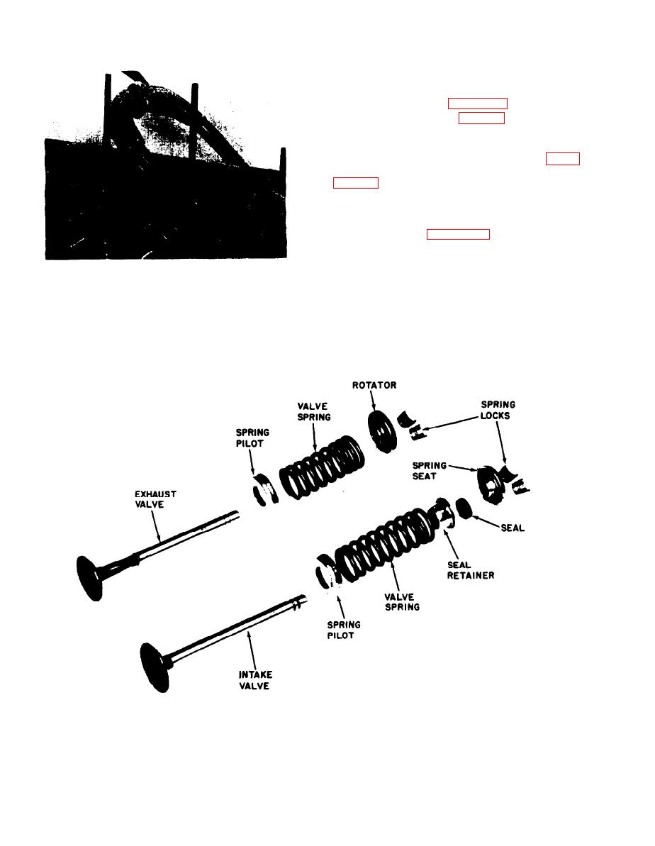
Figure 5-17. Value Parts Removed
5-20
|
|
Privacy Statement - Press Release - Copyright Information. - Contact Us |