 |
|||
|
|
|||
|
|
|||
| ||||||||||
|
|
 TM 10-3930-644-14 &p
5. Reconnect hydraulic hoses to cylinder.
7. Lubricate all pressure lube fittings on side shifter
unit.
6. Reinstall lower hanger bars. Torque capscrews
to required value; see tabulation below.
D. ADJUSTMENT
Refer to appropriate Topic for the adjustment of the type
CAPSCREW SIZE
TORQUE VALUE
carriage used.
NOTE
If carriage frame is of the canted
.33"-16 x 1.25"
28-33 lb. ft.
bearing type it must be adjusted
before installation.
.38"-16 x 1.50"
28-33 lb. ft.
.50"-13 x 1.50"
G8-73 lb. ft.
.63"-11 x 1.75"
125-135 lb. ft.
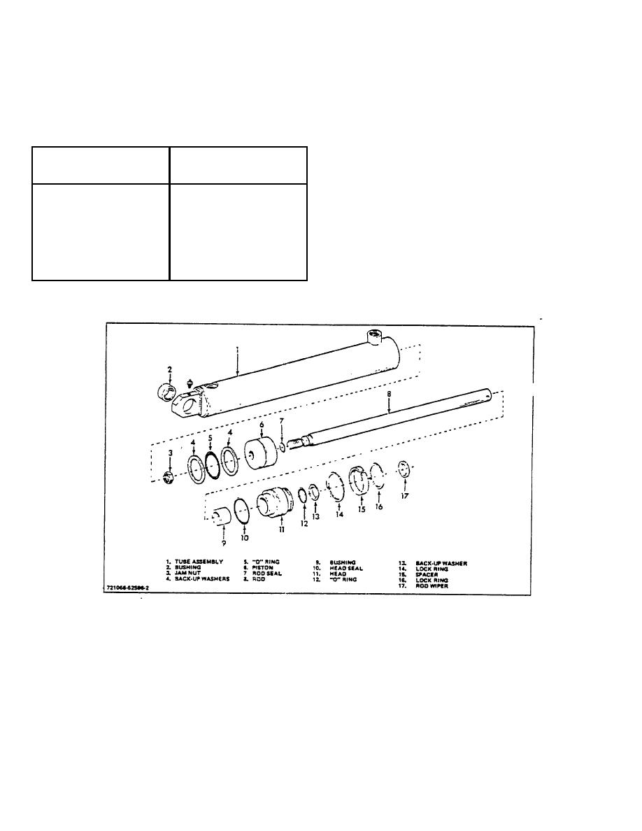
TOPIC 6. SIDE SHIFTER CYLINDER
Figure 8.
A. REMOVAL
3. Disconnect hydraulic hoses from cylinder. Plug
cylinder ports and hydraulic hose ends to
1. Remove cotter pin and rod pin from cylinder rod.
prevent entry of foreign material.
2. Retract cylinder rod far enough to clear rod
4. Remove cotter pin and cylinder retainer pin and
retainer on side shift plate.
lift out cylinder.
3-202
|
|
Privacy Statement - Press Release - Copyright Information. - Contact Us |