 |
|||
|
|
|||
|
|
|||
| ||||||||||
|
|
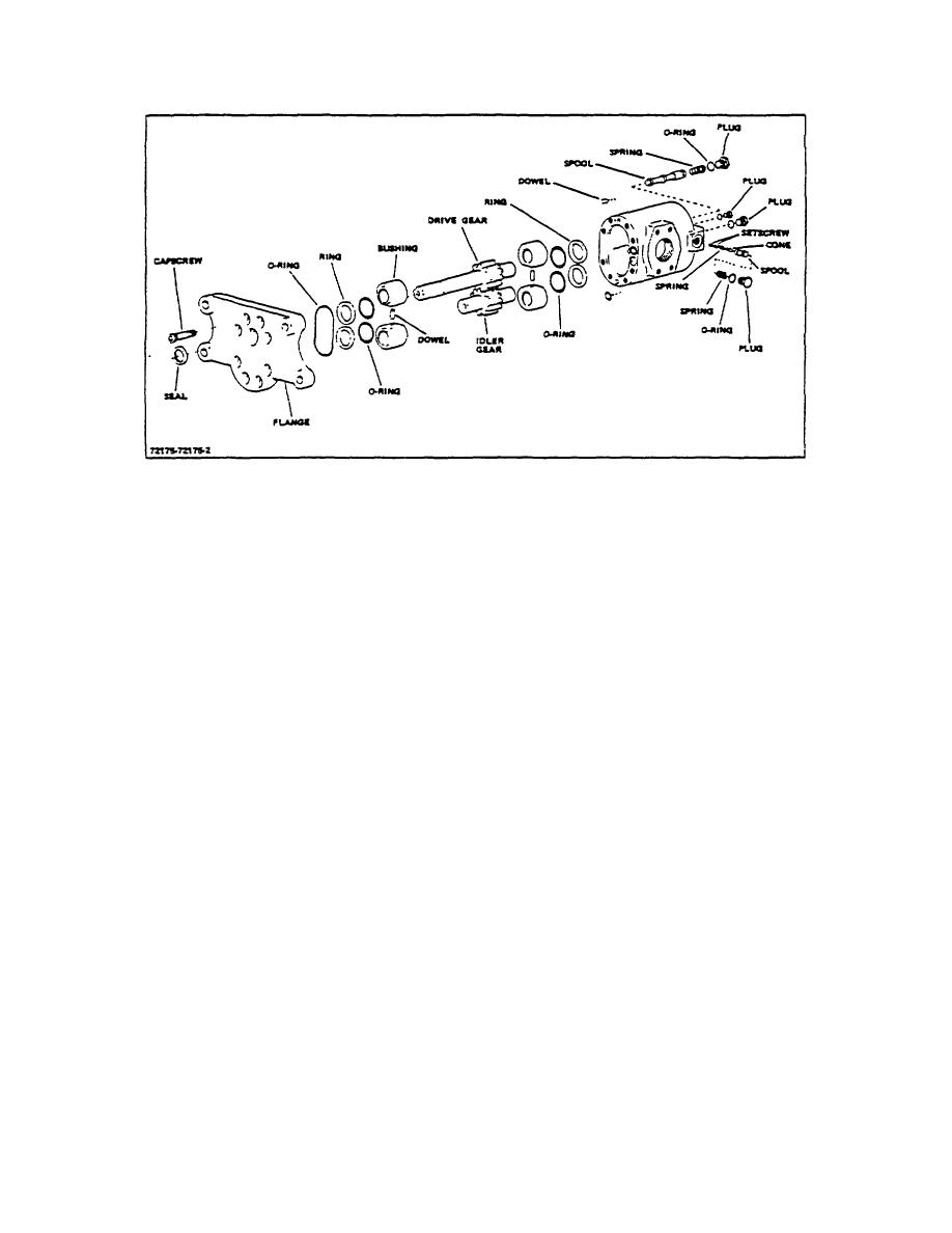 TM 10-3930-644-14&P
Figure 1-1. Hydraulic Pump
Looking at the plate from the pump side,
body. Check diameter of all lands and replace
measure the top left and lower right mounting
spool if any are less than .748. Check the
holes. If the holes are larger than .441 diameter,
balance and flow orifices and clear with a fine
replace the flange. This indicates pump has
wire, if plugged.
been running with mounting bolts loose.
if
flange is to be reused, hone same as body face.
7. Check valve spool spring to see that it is not
bent or deformed. Replace if length is less than
4. Handle pump gears carefully when inspecting to
3-1/2'".
prevent burring the teeth with resultant damage
to the bushings. If the length of the gear is less
8. Inspect the relief valve plunger for wear and
than 1.320, or if gear O.D. is less than 1.754,
erosion and replace, if damaged.
the gear must be replaced. Check gear teeth
ends and remove any burrs with a small, fine
9. If relief valve spring is bent or deformed, replace
hone. If journal surfaces are blackened, and
it. Replace if length is less than 0.30.
can be scratched with a pen knife, they have lost
their case hardening and must be replaced.
E. REASSEMBLY
5. When inspecting the bushings, they must be
Before reassembling pump, lay out all parts in a
handled very carefully to prevent damage, as
sequence in which they were removed and make sure all
this makes them difficult to assemble and
parts are perfectly clean.
reduces their sealing effectiveness. The bore of
the bushing, will be worn slightly oval, must not
1. Place pump face up and install the two body
measure over 0.381 at the largest reading. The
dowels, tapping them in place with a plastic
length of the bushing must not measure under
hammer. Coat body bores with light oil.
1.055. Minor cuts or scratches can be removed
by honing in a circular motion with an extra fine
2. Place the bushing O rings and the backup rings
stone. Be sure sharp edge between face of
on the shoulder at the rear of the rear bushings.
bushing and the O.D. is not broken. Erosion on
Hold in place with grease, if necessary. Place
the face of the bushing near the rectangular land
the bushing dowel in the holes in the flat side of
and in the lube oil slot indicates dirt in the
the bushings and holding the bushings together,
system.
carefully align then and slide them, O Ring side
down, into the bores. Coat faces and bores of
6. Wash valve spool and dry with compressed air.
the bushings
It should slide freely in and out of its bore in the
3-180
|
|
Privacy Statement - Press Release - Copyright Information. - Contact Us |
