 |
|||
|
|
|||
|
|
|||
| ||||||||||
|
|
 TM 10-3930-644-14&P
7. Fill seal with grease and install it on pivot arm
pin.
8. Install washer and start new nut on pivot arm
pin.
9. Use a torque wrench and continue to tighten nut.
Note torque reading while advancing lower cone
to its seated position.
You will notice an
increase in the torque when the lower cone
starts to seat. Continue to tighten nut until
torque is 15-25 lb-ft greater than previously
noted before lower cone started to seat.
10. Check rotational bearing torque. Rotate pivot
arm back and forth several times and take rolling
torque reading. It should require 15-25 lb-ft
torque to rotate pivot arm in either direction.
NOTE
Tie rods must not be connected to
pivot am whenever rolling torque is
checked.
11. If rolling torque is less than 15 lb-in, tighten nut
an additional 5 lb-ft torque and repeat Step 10.
12. If rolling torque exceeds 25 lb-in, back nut off
one full turn. Strike end of pivot arm pin with a
softheaded mallet to unseat bearings and repeat
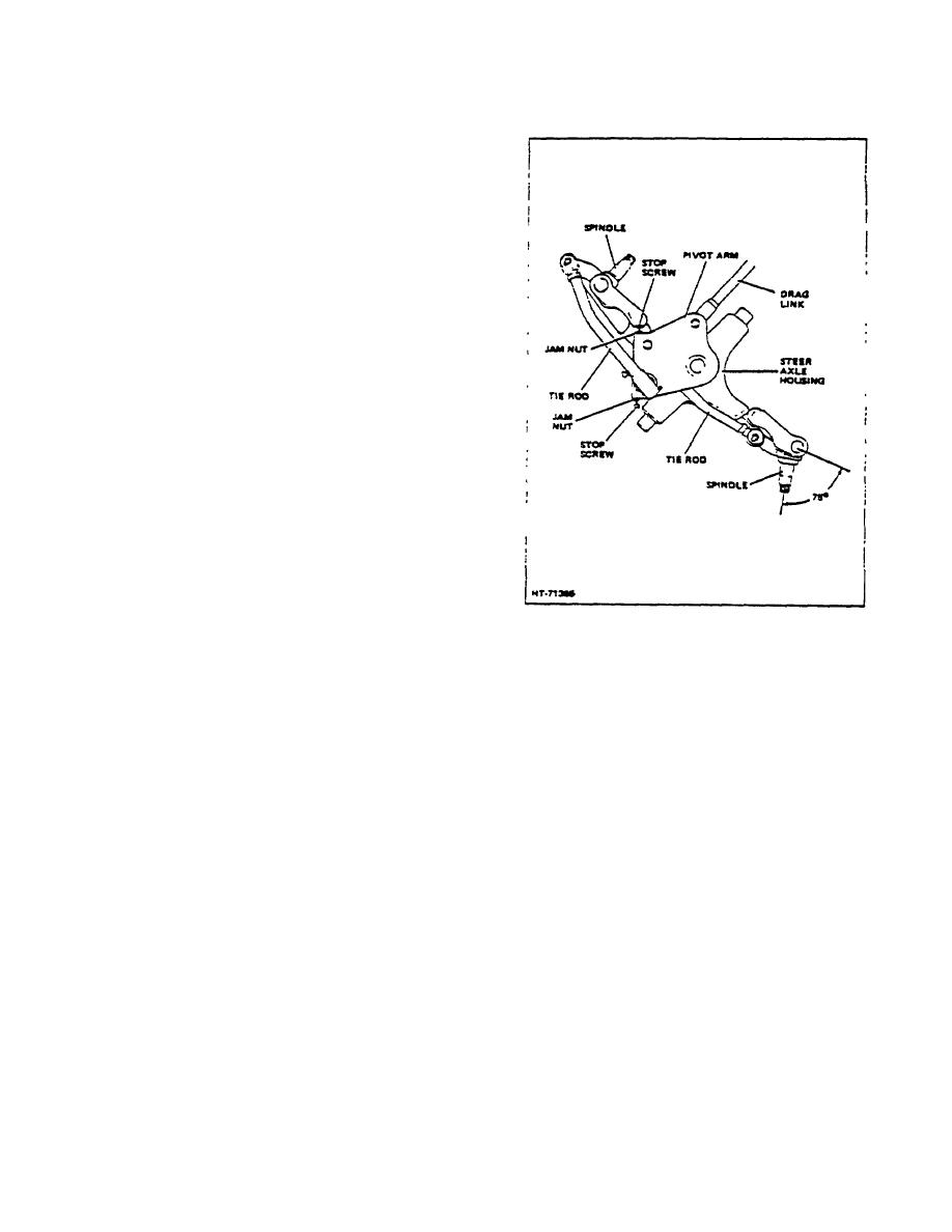
Figure 5. Pivot Arm Stop Adjustment
Steps 9 and 10.
turn and then to full left turn and adjust pivot arm
13. After proper rolling torque is obtained, stake end
stop screw each time.
of nut approximately .030" deep into slot (Fig. 4).
2. Loosen Jam nuts and adjust the pivot arm stops
14. Fill cavity with specified grease until it seeps out
(Fig. 5) to allow 1/2" clearance between the
between pivot am and steer axle housing.
steer wheel and steer axle housing with the
wheels turned full right or full left. Stops should
G. PIVOT ARM STOP ADJUSTMENT
limit travel of wheel spindle to 75 from
centerline of spindle. Tighten stop screw jam
1. Turn steer wheels first to full right
nut to a torque of 2 to 3 lb-ft.
3-162
|
|
Privacy Statement - Press Release - Copyright Information. - Contact Us |