 |
|||
|
|
|||
|
Page Title:
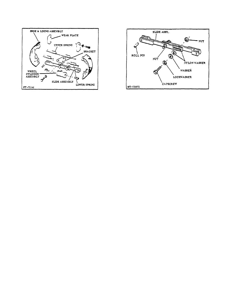
Figure 5. Self-Adjusting Brakes (Exploded View) |
|
||
| ||||||||||
|
|
 TM 10-3930-644-14&P
Figure 5. Self-Adjusting Brakes (Exploded View)
Figure 6. Brake Self-Adjuster
1. Remove upper and lower shoe return springs.
4. Clean inside of backing plate, brake drum and
other parts to be assembled.
2. Remove brake shoes and adjuster Link as an
assembly.
5. Check wheel cylinders for leakage, even if
cylinder appears to be in good condition. The
3. Drive out roll pins which attach adjuster link to
best practice is to overhaul wheel cylinders
brake shoes. Compress adjuster link by placing
when new brake shoes are installed.
one end on a solid surface and tapping other
end with a wooden mallet or a block of wood
6. Place shoe and link assembly in a place and
until fully compressed.
install springs. Install wheel assembly in direct
reversal of removal procedure. While turning
F. INSTALLATION
wheel SLX times in each direction, torque
retaining out to a maximum of 50 ft. lbs., then
To install shoes with new ling, proceed as follows:
back nut off 30' minimum -60 maximum to allow
cotter pin installation.
1. If
self-adjusted
link
is
inadvertently
disassembled, it must be reassembled exactly
7. The first time brake pedal is depressed after
as originally constructed (Figure 6). Torque
installing new shoes automatically sets the
capscrews to 14 16 inch lbs., and lock outs to 29
adjustment.
inch lbs. Slip resistance must be from 250 to
300 lbs. and link should be fully retracted when
Drive wheels should be removed periodically
assembly is completed.
until approximate wear period for brake lining
can be determined. No further adjustment is
2. Attach adjuster link to brake shoes with roll pins.
required after shoes are replaced.
3. Make certain backing plate is secured tightly to
CAUTION
axle, also that it is nor sprung or damaged.
NEVER apply pressure to brake pedal
until drive wheel brakes and wheels
are completely assembled.
3-150
|
|
Privacy Statement - Press Release - Copyright Information. - Contact Us |