 |
|||
|
|
|||
|
|
|||
| ||||||||||
|
|
 TM 10-3930-644-14&P
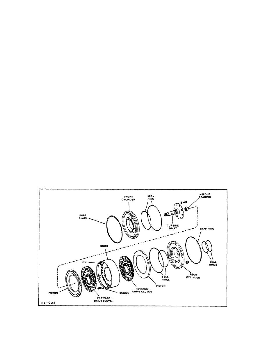
TOPIC 3. DRUM ASSEMBLY
The drum assembly is comprised of a drum, the forward
stator support to converter housing. It may be
The
necessary to tap the pump assembly with a
clutches are engaged by oil pressure applied behind the
rawhide hammer to free it from the gasket. (See
pistons which causes engagement with the drum. The
Figure 1-4.)
unit operates in oil at all times, both for cooling and
lubrication.
4. Lay the transmission on the gear case side as
shown in Figure 1-5. Remove the capscrews
It is necessary to remove the transmission in order to
which mount the converter housing to the gear
gain access to the drum assembly for service or repair.
case. Then attach a chain to the housing and
(Refer
to
TRANSMISSION
REMOVAL
and
remove the housing and drum assembly as a
DISASSEMBLY
unit, taking care not to damage the seal rings in
collector ring on gear case (Figure 1-5).
A. REMOVAL
To remove the converter housing from the drum,
1. Thoroughly clean outside of transmission to
remove the snap ring on the turbine shaft and
prevent possibility of contamination.
slide the housing from the drum assembly. The
bearing will remain in housing. (See Figure 1-6.)
2. With transmission out of truck, remove the
capscrews from valve assembly and remove
B. DISASSEMBLY
valve assembly.
Remove valve to prevent
damage
to
valve
during
disassembly
The front and rear clutch assemblies are balanced. Two
procedures.
lines are etched on rear clutch cylinder to indicate
correct alignment of the cylinder with the piston. One
3. Slide converter off the turbine shaft. Then mark
etched line is
the pump and the housing to ensure the proper
reinstallation, and remove capscrews holding
the pump and
Figure 3-1. Drum Assembly
R-171-1
3-127
|
|
Privacy Statement - Press Release - Copyright Information. - Contact Us |
