 |
|||
|
|
|||
|
|
|||
| ||||||||||
|
|
 TM 10-3930-644-14&P
3. Momentarily flash a jumper lead from the
solenoid motor terminal to the solenoid frame.
This will shift the pinion into cranking position
and it will remain so until the battery is
disconnected.
4. Push the pinion back toward the commutator
end to eliminate slack movement.
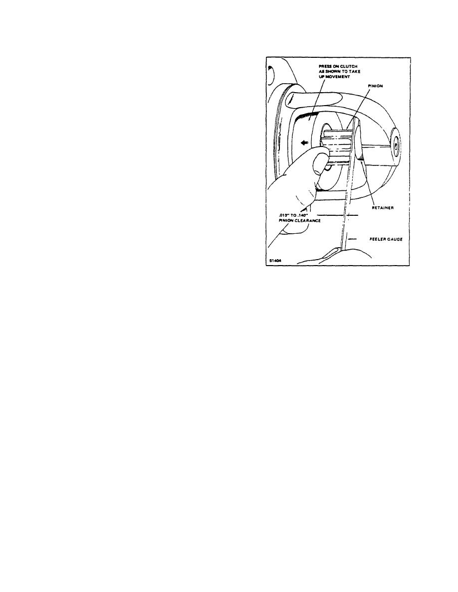
5. Measure the distance between pinion and pinion
stop (See Figure 3-8). Pinion clearance should
be .010" to .140".
J. STARTER MOTOR INSTALLATION
1. Insert drive end of starter motor in flywheel
housing. If drive mechanism is fully extended,
mesh pinion gear with flywheel ring gear. Install
mounting bolts and tighten securely.
2. Connect all electrical leads to either starter
m8tor or starter solenoid.
3. Close right hand side panel and lower operator's
seat.
Figure 3-8. Checking Pinion Clearance
R-146-1
3-97
|
|
Privacy Statement - Press Release - Copyright Information. - Contact Us |