 |
|||
|
|
|||
|
|
|||
| ||||||||||
|
|
 TM 10-3930-644-14&P
3. High Speed (Main Metering) System. As the
choke plate opens to prevent over-choking. As
throttle is advanced to approximately one-
the engine warms, the choke must be opened
quarter opening, the amount of air passing
manually to the wide open position.
through the venturi creates a suction on the tip
of the main discharge jet. This suction causes
the fuel to flow from the fuel chamber through
the main jet and into the main discharge jet
where it is mixed with air admitted by the well
vent jet. This mixture is then discharged into the
air stream through the discharge jet, see Figure
5. The main jet controls the fuel delivery from
about one-quarter to full throttle opening. To
maintain a proper mixture ratio a small amount
of air is admitted through the well vent into the
discharge jet through air bleed holes located in
the discharge jet at a point below the level of
fuel in the metering well.
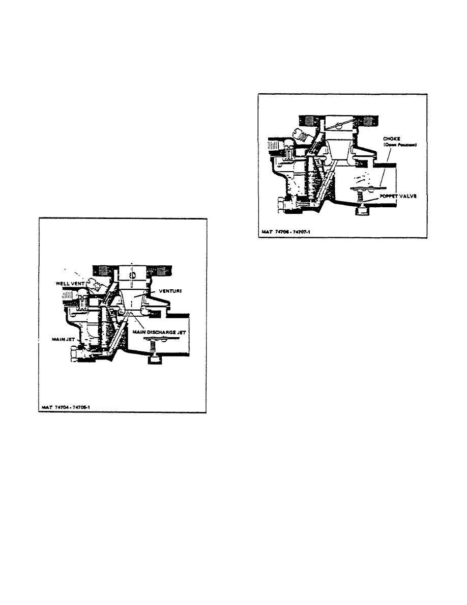
Figure 6. Choke System
C. DISASSEMBLY
1. Separation of Throttle and Fuel Bowl Bodies.
a. Remove hex head plug and filter screen (if
used) from side of throttle body.
b. Remove four bowl to body screw and
lockwasher assemblies.
c. Raise throttle body slightly and separate
gasket from fuel bowl flange, then lift off
throttle body assembly being careful not to
damage float assembly.
2. Disassembly of Throttle Body.
a. Press screwdriver against float axle at
Figure 5. High Speed System
slotted side of float hinge bracket and
force axle through slotted side of bracket,
4. Choke System. Closing the choke plate when
then remove axle with fingers from
starting a cold engine restricts the air entering
opposite side of bracket and remove float
the carburetor through the air cleaner and
assembly.
creates an increase in suction on the jets. This
increase in suction causes more fuel to be
b. Remove fuel valve needle, bowl to body
drawn into the engine and provides a richer
casket and venturi.
mixture necessary for starting a cold engine. As
soon as the engine starts to operate, the spring-
loaded poppet valve located within the
3-66a
|
|
Privacy Statement - Press Release - Copyright Information. - Contact Us |
