 |
|||
|
|
|||
|
|
|||
| ||||||||||
|
|
 TM 10-3930-644-14&P
TOPIC 4a. CARBURETOR (SRT)
A. DESCRIPTION
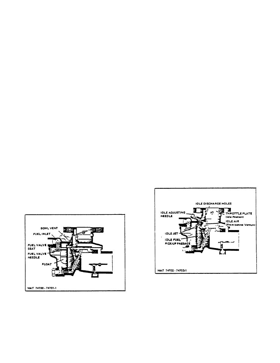
2. Idle System. At idle speed the throttle plate is
advanced slightly to expose the upper idle
The carburetor is of the single barrel updraft design, with
discharge hole to engine manifold vacuum
a single venturi, twin floats, and a semi-concentric fuel
(suction), see Figure 4.
This suction is
bowl to permit operation at quite extreme angles without
transmitted to the idle jet through a passage
flooding or starving the engine. It is of the "balanced"
connecting the idle discharge holes with the idle
and "sealed" type since all air for fuel bowl ventilation
jet. Fuel for idle is supplied through the main jet
and idle operation must enter through the air cleaner.
to a well at the bottom of the discharge jet. The
The fuel supply system is made up of the threaded fuel
fuel for idle flows out of this well through a
inlet, fuel valve (needle and seat), float assembly and
restricted drilling at the bottom of the idle fuel
the float chamber. The idle system consists of two Idle
pick-up passage. From here the fuel is metered
discharge holes, idle air passage, idle adjusting needle,
through the idle jet calibration before entering
idle jet, and fuel pick up passage. The high speed (main
the vacuum passage leading to the idle
metering) system consists of the venturi, main jet, main
discharge holes. As the fuel leaves the idle Jet
discharge and well vent. Some models also include a
it is mixed with air that originates back of (or
main jet adjustment. The choke system is of the semi-
from behind) the venturi. The position of the idle
automatic type and is made up of a choke plate, with a
adjusting needle in this passage controls the
spring loaded poppet valve, mounted on a shaft located
suction on the idle jet and thereby the idle fuel
within the air intake and operated externally by a lever
air mixture. Turning the idle adjusting needle IN,
attached to the choke shaft.
(clockwise) results in a greater suction on the
idle jet with a smaller amount of air admitted to
B. OPERATION
give a richer mixture. Turning the needle OUT
(counterclockwise) increases the amount of idle
1. Fuel Supply System. Fuel under pressure is
air admitted and reduces the suction on the idle
supplied through the fuel inlet fitting, fuel valve
jet resulting in a leaner mixture. This idle fuel-air
(needle and seat) to the float chamber, see
mixture is then discharged through the idle
Figure 3.
The float in the float chamber
discharge holes into the air stream.
automatically regulates the opening through the
fuel valve (needle and seat) to maintain the
proper level of fuel in the fuel bowl and to meet
the demands of the engine according to engine
load and speed.
Figure 4. Idle System
Figure 3. Fuel Supply System
3-66
|
|
Privacy Statement - Press Release - Copyright Information. - Contact Us |
