 |
|||
|
|
|||
|
Page Title:
TOPIC 4. CARBURETOR (TYPE II) (PRT) |
|
||
| ||||||||||
|
|
 TM 10-3930-644-14&P
TOPIC 4. CARBURETOR(TYPE II) (PRT)
A. DESCRIPTION
The carburetor is of the single barrel updraft design, with
a single venturi, two floats, and a semi-concentric fuel
bowl to permit operation at quite extreme angles without
flooding or starving the engine. It is of the "balanced"
and "sealed" type since all air for fuel bowl ventilation
and idle operation must enter through the air cleaner.
The fuel supply system is made up of the threaded fuel
inlet, and the float chamber. The idle system consists of
two idle discharge holes, idle air passage, idle adjusting
needle, idle jet, and fuel pickup passage. The high
speed (main metering) system consists of the venturi,
main jet, main discharge and well vent. The choke
system is of the semi-automatic type and is made up of
a choke plate, with a spring loaded poppet valve,
mounted on a shaft located within the air intake and
operated externally by a lever attached to the choke
shaft.
B. OPERATION
1. Fuel Supply System.
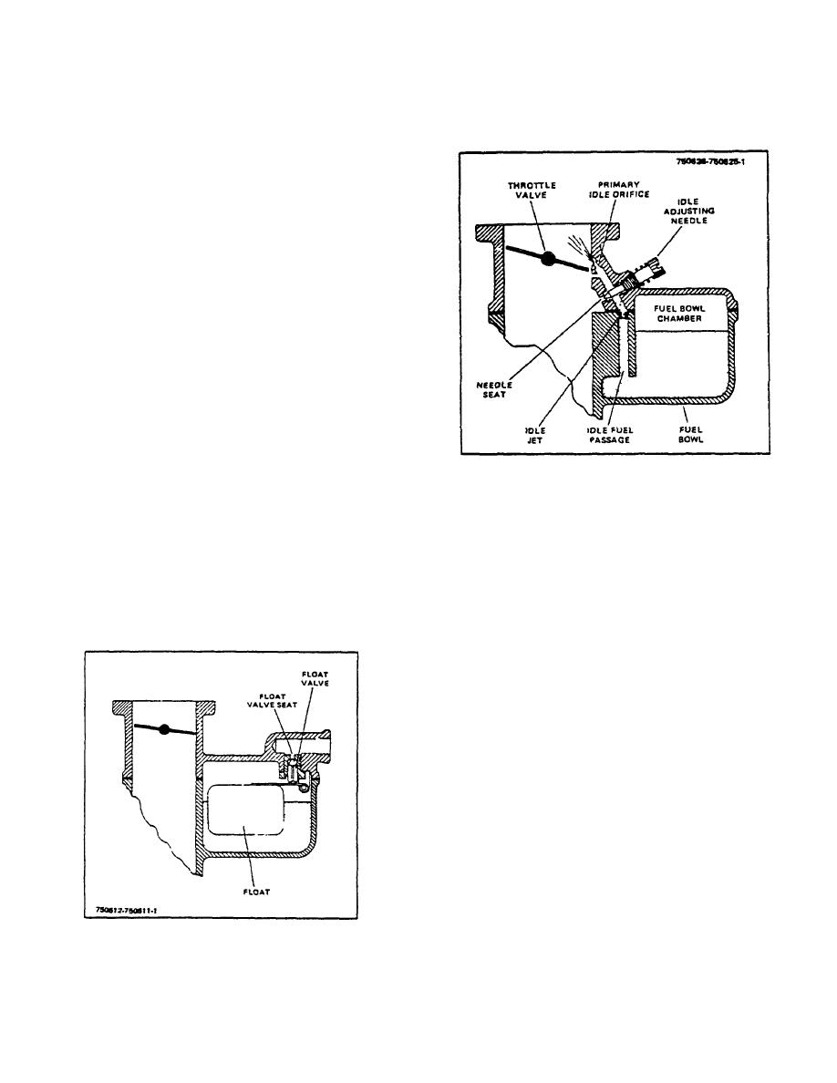
Figure 4-2. Idle System
Fuel under pressure is supplied through the fuel
2. Idle System.
inlet fitting, fuel valve (needle and seat) to the
float chamber, see Figure 4-1. The float in the
The idle system controls the flow of fuel at idle
float chamber automatically regulates the
speed and at slow speeds until the throttle is
opening through the fuel valve (needle and seat)
opened wide enough to allow the power fuel
to maintain the proper level of fuel in the fuel
feed system to function.
bowl and to meet the demands of the engine
according to engine load and speed.
When the throttle valve (Fig. 4-2) is in the idle
position the edge of the valve is between the
primary idle orifice and the secondary idle
orifice. With the valve in this position the air
pressure (manifold vacuum) at the primary idle
orifice is lower than the air pressure in the fuel
bowl chamber and fuel is forced from the fuel
bowl into the Idle fuel passage. As the fuel
travels through the idle fuel passage it passes
through the metering orifice of the idle jet to the
point where it is combined with air entering
through the idle adjusting needle seat. The
mixing of air with gasoline helps to atomize the
fuel and the process is repeated at the
secondary idle orifice as the fuel travels through
the idle fuel passage. As this rich mixture of fuel
and air emerges from the primary idle orifice it is
reduced to correct proportions by the air which
passes around the throttle valve since this valve
must be slightly open to permit the engine to
idle.
The resultant mixture is correct for
Figure 4-1. Fuel Supply System
operating engine at idle speed, provided the idle
adjusting needle is properly adjusted.
R-123-1
3-59
|
|
Privacy Statement - Press Release - Copyright Information. - Contact Us |
