 |
|||
|
|
|||
|
Page Title:
TOPIC 8. PISTON AND CONNECTING RODS |
|
||
| ||||||||||
|
|
 TM 10-3930-644-14&P
TOPIC 8. PISTON AND CONNECTING RODS
A. DESCRIPTION
replace bearing shells with new ones. Inspect pistons
The pistons used are aluminum and use four rings two
for score marks or for worn, stuck or broken rings.
compression rings, one scraper ring and one three-piece
Inspect for excessive carbon deposits on piston walls
oil control ring.
and in ring grooves. Check ring grooves for excessive
wear and worn edges. Check pistons for cracks.
The rifle drilled forged connecting rods are precision
ground at the large end to receive precision type thin-
When fitting replacement pistons and rings, four different
wall bearing shells (Figure 8-1).No shims are used, since
precision checks should always be made: check ring
oversize bearing shells are available to provide a tight fit.
gap, check ring to land clearances, check pin clearance
in piston boss, and check piston skirt clearance.
A bronze bushing is burnished and diamond bored in
place in the upper end of the connecting rod.
C. INSPECTION
Pistons are available in .010", .020", .030" and .040"
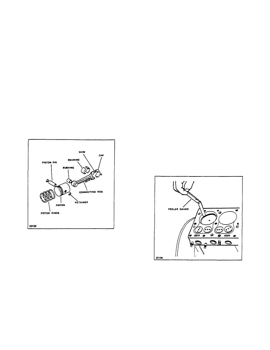
1. Checking Piston Ring Gap
oversizes to provide correct tolerances when cylinders
Check the piston rings in the cylinders for gap.
are bored and honed due to wear. Piston rings are
To do this, insert a piston in the cylinder bore in
available in the same oversizes to match specific
an inverted position and then insert each ring,
pistons.
one at a time, about 2" down in the bore and
bring the bottom edge of the piston up against
the ring to square it up in the cylinder bore
(Figure 8-2).
Check the gap between the ends of the ring with
a feeler gauge in accordance with specifications
shown in TOPIC 1. FITS AND TOLERANCES.
Figure 8-1. Piston and Connecting Rod Assembly
B. REMOVAL
Piston and connecting rod replacement is accomplished
with the engine out of the truck. (Refer to TOPIC 6.
CRANKSHAFT AND CRANKSHAFT COMPONENTS).
Figure 8-2. Checking Ring Gap (Typical)
All piston and rod assemblies are removed from the top
Those rings with gaps less than specified should be
of the bore. Before removing, however, it is important
carefully dressed off with a flat cut file until the correct
that the ridge at the top edge of the bore be removed by
clearance is obtained. Fairly wide ring gaps, near the
using a Ridge Cutting tool. If the same bearings are to
top limit, are far less detrimental to engine
be reused, be sure the bearing shells are kept in order
performance than gaps which are too tight. The two
with respect to which rod they go in, which is top and
top rings require greater end gap than the lower rings
which is bottom. However, it is usually good practice to
because they are subjected
R-104-1
3-27
|
|
Privacy Statement - Press Release - Copyright Information. - Contact Us |
