 |
|||
|
|
|||
|
|
|||
| ||||||||||
|
|
 TM 10-3930-644-14&P
TOPIC 3. FORKS
A. DESCRIPTION
Basically, there are two types of lift forks; the shaft style
(Fig 8) which pivots on a horizontal support shaft, and
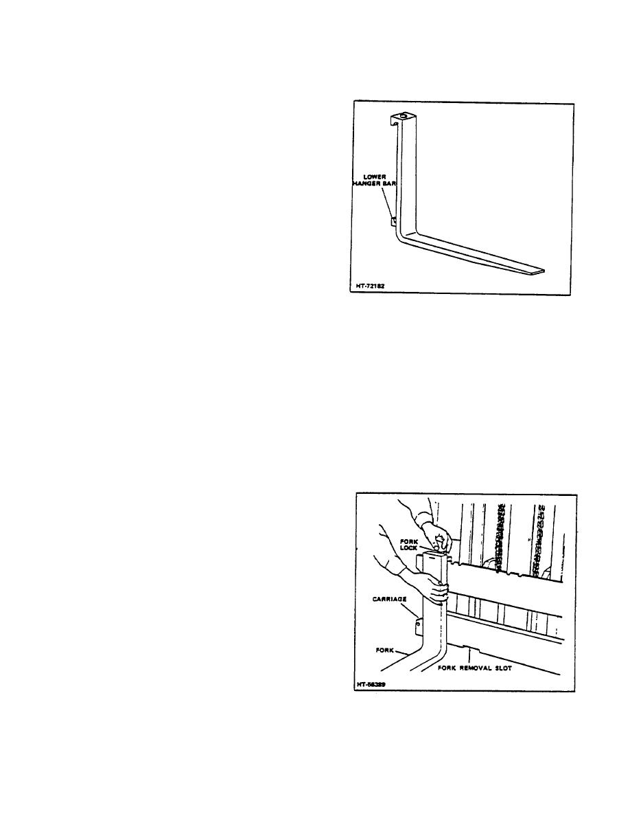
the more commonly used hook style fork (Fig 9) which
hooks into notches along the top edge of the fork
carriage.
The standard or hook type fork will be
discussed here. Any differences will be noted in shaft
type removal and installation.
The forks should always be adjusted on the carriage to
obtain the optimum balance in proportion to the width of
the anticipated loads.
A fork lock (Fig 10), is installed in the top of each of the
hook type forks to hold it in position in one of the notches
along the top bar of the carriage. To change the fork
location, pull up on the lock and move fork to the left or
right. Allow fork lock to seat in the notch nearest to
Figure 9. Hook Style Fork
location chosen.
3. If fork is defective, then replace with same type
The forks can be easily removed from the carriage by
and capacity rated fork.
releasing the locks and aligning each fork with the wide
removal slot (see Fig 10), at the bottom of the fork
D. INSTALLATION
carriage. (Refer to following REMOVAL procedures for
detailed instructions.)
1. Carefully lift fork up onto upper carriage
mounting slot, then slowly lower until back of
CAUTION
fork rests against carriage face and bottom fork
Naturally, the weight of each fork
hook passes through lower carriage cutout.
depends upon its size. Therefore,
2. Release the fork loc k pin and slide fork left or
exercise caution while fork is being
right until properly positioned for anticipated load
removed from the carriage to avoid
clearance/balance requirements.
injury to personnel and to prevent
damage to the equipment.
B. REMOVAL
1. Lower fork carriage until base of fork just clears
the floor.
2. Release the fork lock pin and slide fork to a
position over the cut-out in the lower carriage
bar. (Fig 10.)
3. Tilt the lower portion of the fork forward and up,
releasing the lower hanger (Fig 9), from the
lower carriage bar.
4. Refer to cautionary note in Paragraph A above,
and lift fork off upper carriage bar.
C. SERVICE
1. Inspect hook fork and locking mechanism for
any evidence of wear or damage.
2. If locking mechanism is worn or damaged,
Figure 10. Fork Adjustment and Removal
remove and replace it as a unit.
2-104
|
|
Privacy Statement - Press Release - Copyright Information. - Contact Us |