 |
|||
|
|
|||
|
Page Title:
TOPIC 2. SIDE SHIFTER (PRT only) |
|
||
| ||||||||||
|
|
 TM 10-3930-644-14&P
TOPIC 2. SIDE SHIFTER (PRT only)
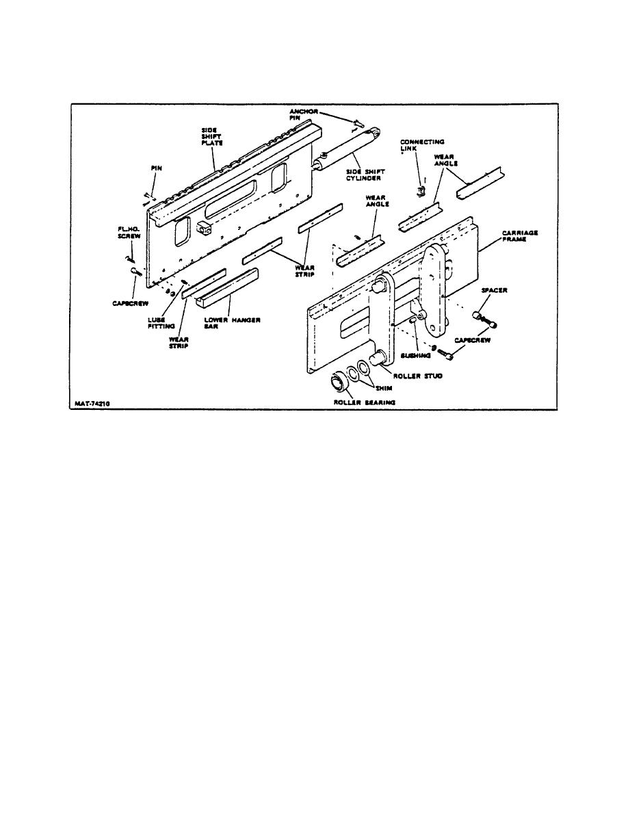
Figure 7. Side Shift Components
A. DESCRIPTION
C. SIDE SHIFTER CYLINDER REMOVAL
The integral side shift carriage enables the operator to
1. Remove cot ter pin and rod pin from cylinder rod.
rapidly and accurately position loads and to make more
efficient use of available storage areas with a minimum
2. Retract cylinder rod far enough to clear rod
of lift truck jockeying.
retainer on side shift plate.
The cylinder is enclosed within the steel structure of the
3. Disconnect hydraulic hoses from cylinder. Plug
carriage frame, minimizing the possibility of damage.
cylinder ports and hydraulic hose ends to
prevent entry of foreign material.
Wear strips and angles are provided which virtually
eliminate sliding friction. Several grease fittings are
4. Remove cotter pin and cylinder retainer pin and
installed at the wear points to ensure proper lubrication.
lift out cylinder.
Lubricate these fittings every 50 hours of operation.
D. SIDE SHIFTER CYLINDER INSTALLATION
B. REMOVAL/INSTALLATION
1. Install anchor pin and cotter pin to cylinder and
First disconnect hydraulic hoses at junction block on
carriage frame.
carriage frame, then refer to TOPIC 1, and perform
applicable removal (or installation) procedures.
2. Connect hydraulic hoses.
3. Extend cylinder rod and install retaining pin and
NOTE
cotter pin.
See TOPIC 1 for bearing adjustment.
2-103
|
|
Privacy Statement - Press Release - Copyright Information. - Contact Us |
