 |
|||
|
|
|||
|
|
|||
| ||||||||||
|
|
 TM 10-3930-644-14&P
wheel six times in both directions, then
f. To replace spindle, align the spindle in the
drive housing and replace the washer and
back nut off 30 minimum to 60 maximum
so cotter pin can be installed.
locknut. Tighten the nut until the spindle
fully seats, then install the cotter pin.
TORQUE VALUES:
g. Install the dust shield and the wheel
assembly.
ACC40 PS ..........120 lb ft
h. Tighten wheel bearing nuts as follows:
ACP40 PS ..........120 lb ft
Using a torque wrench, tighten nuts in
accordance with chart below; just before
reaching maximum torque, turn each
TOPIC 2. HYDRAULIC BRAKES
The brake system consists of a mechanically activated
hydraulic master cylinder with heavy duty brake lines
transmitting hydraulic pressure to the brake wheel
cylinders located behind a dust shield in each of the
drive wheels.
For a complete description of the
hydraulic braking system and service procedures, refer
to HYDRAULIC BRAKE Section.
TOPIC 3. DIFFERENTIAL
A. DESCRIPTION
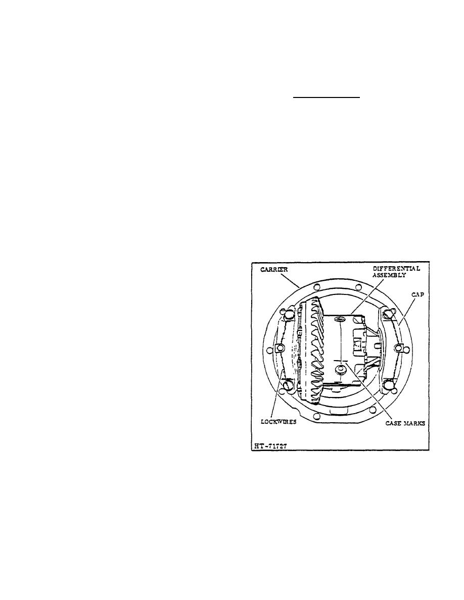
The differential case and carrier consists of two parts,
the carrier assembly and the differential assembly. (See
Figure 14.) The carrier assembly is mounted at the
center of the drive unit housing (See Figure 2) and
encloses the pinion gear from the drive shaft. The bevel
ring gear is bolted to the differential case and the case in
turn houses the spider gears.
It is the purpose of the differential and carrier assembly
to accept and translate the driving torque from the drive
shaft coupling to the drive wheels of the lift truck, thus
moving the truck in a forward or reverse direction. The
following procedure is recommended to remove the
differential assembly from the carrier.
B. REMOVAL
1. Remove the drive wheels; refer to DRIVE
WHEEL REMOVAL.
2. Remove the jackshafts; refer to JACKSHAFT
REMOVAL.
3. Remove U-Joint and drive shaft coupling; refer
Figure 14. Differential and Carrier Assembly
to U-JOINTS. REMOVAL.
2-69
|
|
Privacy Statement - Press Release - Copyright Information. - Contact Us |