 |
|||
|
|
|||
|
|
|||
| ||||||||||
|
|
 TM 10-3930-644-14&P
TOPIC 7. IGNITION COIL
A. DESCRIPTION
All the ignition cabling in the high tension circuit (coil to
distributor to spark plugs) is neoprene covered and is
The purpose of the high voltage ignition coil is to deliver
resistant to oil, grease, battery acid. This type of
high voltage surges to the spark plugs, via the
insulation also helps to prevent current losses.
distributor.
The ignition coil accomplishes this by
stepping up e primary input voltage of 12 V.D.C. to a
8. SERVICE
surge of about 20,000 V.D.C.
through normal
transformer action.
The ignition coil requires no particular service other than
an occasional operational performance check. Also
The coil consists of a primary and a secondary winding.
check electrical contact points for cleanliness and
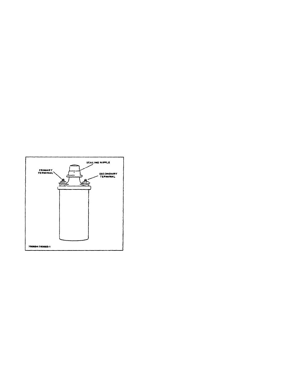
(See Figure 7-I) The primary winding contains about 200
tightness of connection. The coil can only be tested on a
turns of heavy wire, and the secondary winding contains
reliable coil testing machine; however, if the engine is
about 20,000 turns of very fine wire To concentrate the
quick starting and smooth running it can be assumed
magnetic field, these windings surround a soft iron core
that the ignition coil is performing satisfactorily.
composition and are enclosed by a soft iron shell. The
entire assembly is built into a one piece steel coil case
C. REMOVAL
which is oil filled and hermetically sealed by the cap and
gaskets.
This construction prevents moisture from
I. Disconnect and label primary lead, resistor lead
entering the call and also permits faster dissipation of
and condenser lead attached to cap of ignition
the generated heat.
coil.
2. Pull high tension (secondary) wire out of center
of cap.
3. Loosen securing clamp and remove ignition coil.
4. Clean exterior of coil assembly with an
acceptable cleaning solvent. Check that primary
connectors are free of dirt and grime and
provide a good electrical connection.
5. Remove sealing nipple and check for cracks.
Replace, if damaged.
6. Inspect high tension terminal for foreign deposits
and clean,-+f necessary.
7. Inspect entire case for cracks or oil seepage.
Replace, if damaged.
8. Place ignition coil on ignition coil tester and
Figure 7-1. Ignition Coil
check for proper voltage output and voltage
breakdown. Take action as indicated by test
The coil has two primary terminals marked "+" and "-" on
results.
the exterior cap. (The proper polarity is noted on the
ignition wiring diagram.) The coil is generally mounted as
D. INSTALLATION
near as possible to the distributor in order to keep the
interconnecting high tension lead as short as possible.
1. Insert ignition coil in retaining clamp and secure
(This reduces the possibility of a high voltage arc
clamp.
between the wire and any chassis (ground) points it
might otherwise contact.)
2. Insert high tension lead in center of ignition coil
cap. Press down firmly and feel definite snap as
it seats properly. Ensure that sealing nipple is
pressed firmly against coil cap shoulder.
2-30
|
|
Privacy Statement - Press Release - Copyright Information. - Contact Us |
