 |
|||
|
|
|||
|
|
|||
| ||||||||||
|
|
 TM 10-3930-638-24&P
3-9. ALTERNATOR TROUBLESHOOTING (cont)
MALFUNCTION
TEST OR INSPECTION
CORRECTIVE ACTION
2. IMPROPER OUTPUT CURRENT
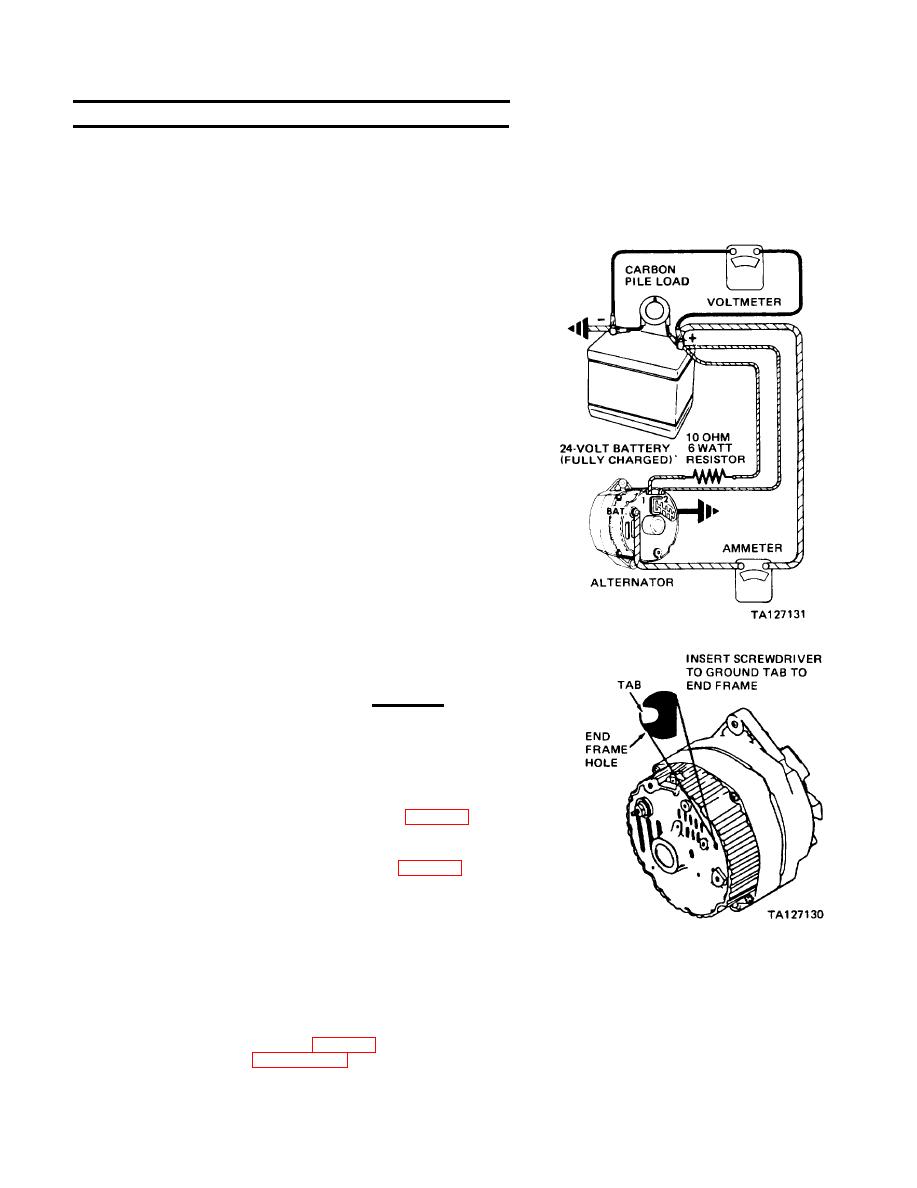
Connect test set-up to alternator as illustrated.
Step 1.
Operate alternator at moderate speed and adjust carbon
pile for maximum indication on ammeter.
Note ammeter indication.
a. If ammeter indicates 27 to 47 amperes, and volt-
meter indicates less than 31 Vdc, alternator
operation is normal.
b. If ammeter does not indicate 27 to 47 amperes,
proceed to step 2.
Step 2.
CAUTION
Tab is within 3/4 inch of casting surface. Do not
force screwdriver deeper than one inch into alter-
nator end frame.
Insert screwdriver into test hole in end frame and
ground tab as shown; then repeat step 1.
a. If ammeter indicates 27 to 47 amperes, check
field winding and regulator (para 3-12).
b. If ammeter does not indicate 27 to 47 amperes,
check the alternator field winding, diode trio,
rectifier bridge and stator (para 3-12).
3-10. STARTER AND SOLENOID TROUBLESHOOTING
1. STARTER TROUBLESHOOTING
NOTE
Compare results of starter no-load test (STARTER CRANKS TOO
SLOWLY, para 2-21) with the following chart and then refer to
|
|
Privacy Statement - Press Release - Copyright Information. - Contact Us |