 |
|||
|
|
|||
|
|
|||
| ||||||||||
|
|
 TM 10-3930-634-34
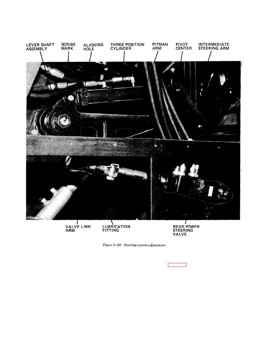
5 - 2 1 . Steering System A d j u s t m e n t
wise from the horizontal. This establishes the straight
This adjustment procedure will provide proper func-
ahead steering (fig. 5-20). The wheels may not-be
tioning of the steering system. Because part dimen-
straight ahead at this point, stop engine.
sions and installation locations may vary from vehicle
c. Check to see that the scribe mark on the pitman
to vehicle, the dimensional settings listed in paragraph
arm lines up with scribe mark on the lever shaft as-
1-7b should be regarded as being of nominal values
sembly. Disassemble and reposition if required.
and a starting point for the following procedure.
d. Place vehicle in 2-wheel steering mode.
a. Lift vehicle so that all wheels are off ground.
e. Disconnect valve link arm at end opposite from
b. Start engine and turn steering wheel to position
valve.
where scribe mark on lever shaft assembly is 60 clock-
|
|
Privacy Statement - Press Release - Copyright Information. - Contact Us |