 |
|||
|
|
|||
|
Page Title:
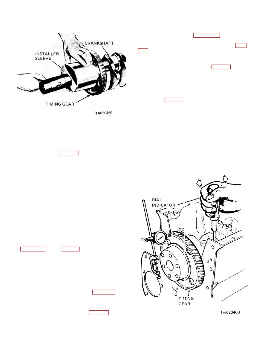
Figure 3-139. Crankskuft timing gear installation. |
|
||
| ||||||||||
|
|
 TM 10-3930-634-34
(b) Place the ring compressor on a wood block,
tapered end up, as shown in figure 3-145.
(c) Stagger the piston ring gaps and make sure
the oil control ring expanders are not overlapped (para
(d) Start the top of the piston straight into the
ring compressor; then, push the piston down until it
contacts the wood block (operation 1, fig. 3-145).
(e) Note the position of the matchmark made on
the liner and place the 1 mer on a wood block.
rod assembly on the liner, so the number on the rod
and cap are alined with the matchmark on the liner
(operation 2, fig. 3-145).
NOTE
The numbers, or number and letter, on the
side of the connecting rod and cap identify
the rod with the cap and indicate the particu-
lar cylinder in which they are used. If a new
connecting rod is to be installed, the same
identification number, or number and letter
(5) After honing, the liner must conform to the
must be stamped or etched in the same loca-
same limits on taper and out-of-round as a new liner,
tion as on the connecting rod that was re-
and the piston-to-liner clearance must be within speci-
placed.
fied limits listed in table 1-1.
(g) Push the piston and rod assembly down into
(6) Discard and replace the seal rings. Replace a
the liner until the piston is out of the ring compressor.
defective liner.
(7) Wipe the inside and outside of the cylinder
liner clean. Make sure the block bore and counterbore
are clean so the liner flange will seat properly.
e. Installation.
(1) Fit Liner in Bore.
(a) Slide the liner into the block until the flange
on the liner rests on the bottom of the counterbore in
the block.
CAUTlON
Do not drop or slam the cylinder liner flange
against the counterbore in the block.
(b) Tap the liner lightly with a soft hammer to
make sure the liner seats in the bottom of the counter-
bore.
(c) Clamp the cylinder liner in place as shown in
tance from the top of the liner flange to top of the
block with a dial indicator.
(d) Matchmark the liner and block with a chalk
or white paint so the liner may be reinstalled in the
same position and in the same bore. Place the match-
mark on the outer edge of the engine serial number
side.
cylinder liner from the block.
(2) Install Piston, Connecting Rod and Liner.
(a) With the piston assembled to the connecting
rod and the piston rings in place (para 3-34) apply a
clean coat of engine oil to the piston, rings and inside
of piston ring compressor tool.
|
|
Privacy Statement - Press Release - Copyright Information. - Contact Us |