 |
|||
|
|
|||
|
|
|||
| ||||||||||
|
|
 TM 10-3930-634-34
ground and checked, thoroughly clean the cylinder
head before installing the valves.
(k) Apply a light coat of engine oil on the valve
compressor tool and secure each valve in position with
stems (36, fig. 3-63) and install the valves in the
two spring locks (33, fig. 3-63). Release tool and in-
cylinder head. If reconditioned valves are used, install
stall the remaining exhaust valves in a similar man-
them in the same port from which they were removed.
ner.
(l) Hold the valves in place with masking tape
and turn the cylinder head right side up on the work
of the exhaust valves after installation.
bench. Place a board under the head to support the
(5) Fuel injector tubes.
valves.
(a) Thoroughly clean the injector tube hole in
(m) Install spring seat, valve spring (35, fig.
the cylinder head; remove all dirt, burrs, or foreign
material that may prevent the tube from seating at the
compressor into the rocker shaft bolt holes in the
lower end or sealing at the upper end.
cylinder head as illustrated in figure 3-70. Depress the
(b) Install a new injector tube sealing ring in the
injector tube counterbore. Use the injector tube instal-
lation tool and install the injector tube in the cylinder
head as illustrated in figure 3-83.
(c) With the injector tube properly positioned in
the cylinder head, flare the lower end of the tube as
follows:
1 Turn the cylinder head bottom side up. Re-
move the tool pilot and thread upsetting die into the
tapped end of the installation tool as illustrated in
2 Use a socket and torque wrench as illus-
trated in figure 3-84 and apply approximately 30 lb-ft
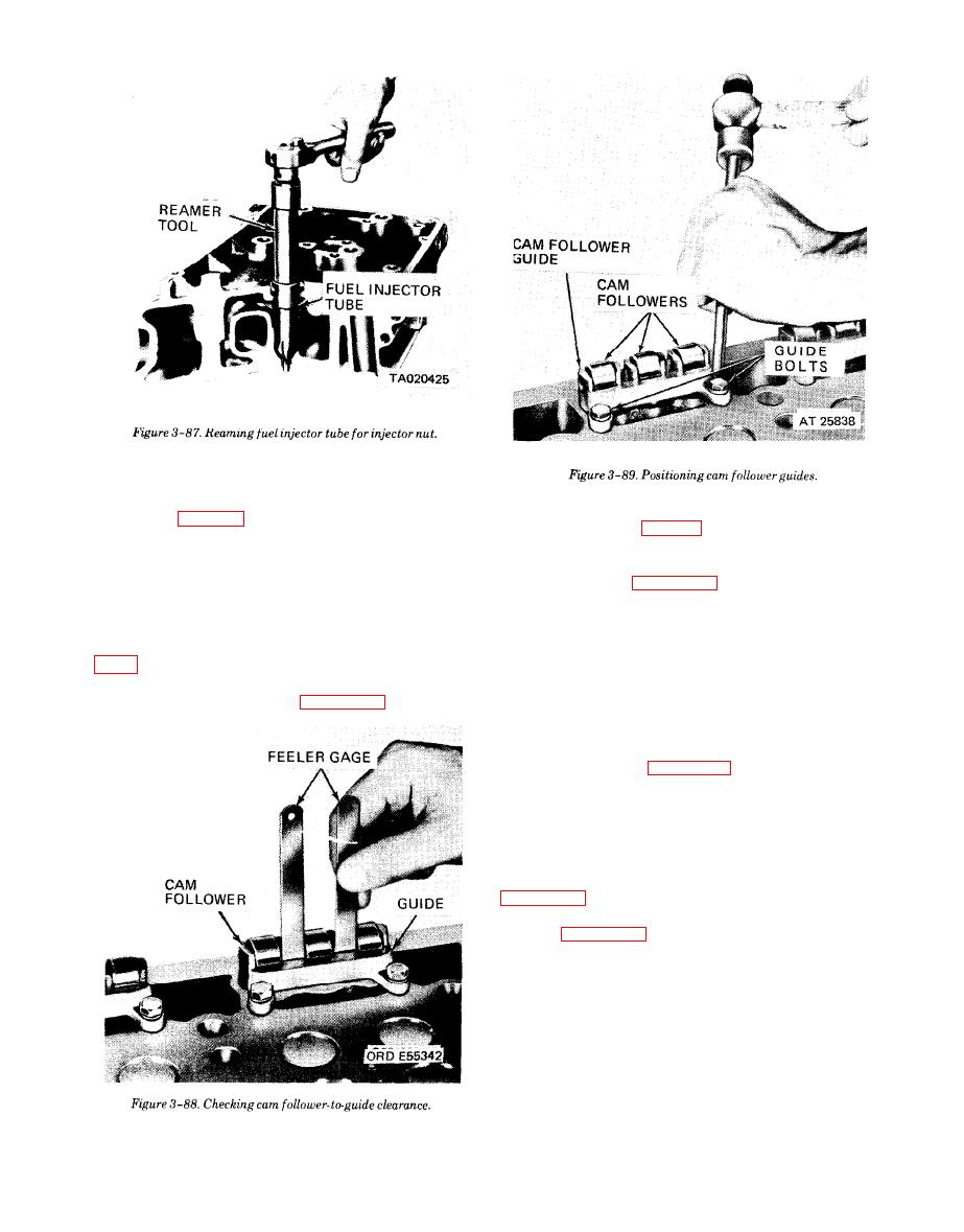
3 Remove the tool and ream the injector.
(d) After the injector tube has been installed in
the cylinder head, it must be finished in three opera-
tions. First, hand reamed, to receive the injector body
nut and spray tip; second, spot faced to remove excess
stock at lower end of injector tube; and third, hand
reamed to provide a good seating surface for lower end
of injector nut.
|
|
Privacy Statement - Press Release - Copyright Information. - Contact Us |