 |
|||
|
|
|||
|
Page Title:
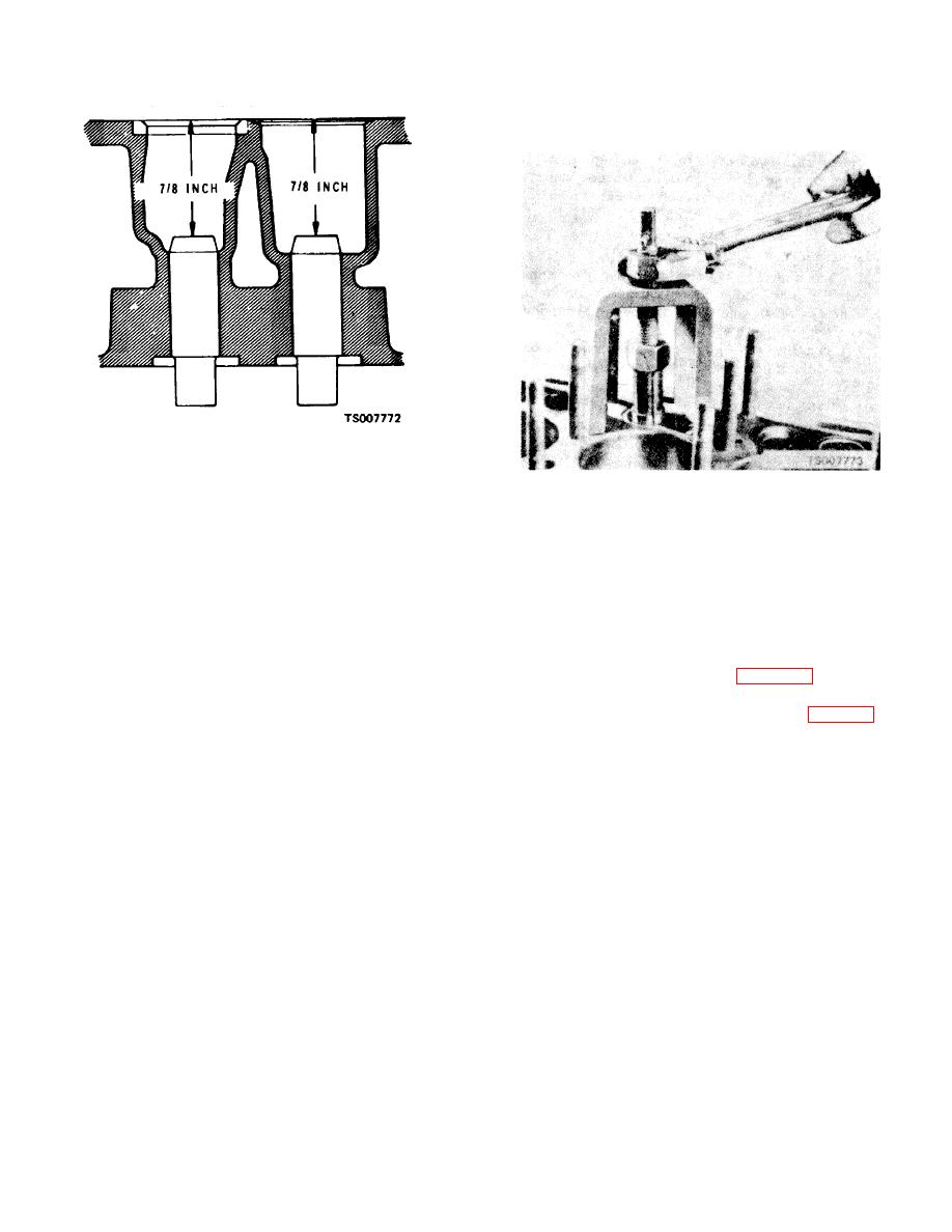
Figure 9-8. Valve Guide Installation Dimensions. |
|
||
| ||||||||||
|
|
 TM 10-3930-632-34
resting against the bottom of the bore. Roll or peen the
valve seat in-place.
Figure 9-8. Valve Guide Installation Dimensions.
CAUTION
Figure 9-9. Pulling Valve Seat Insert.
Do not attempt to ream the valve guides after
seating them. Guides are pre-reamed and
h.
Check the valve springs for cracks and
coated. Further reaming will remove the coating.
distortion. Test compression strength with a spring
tester. Compression, strength must be as follows:
g.
Check the exhaust seat inserts for cracks or
loose mounting. Pull out faulty valve seat inserts (fig. 9-
Length
Load (minimum)
9). Replace valve seats with new 0.010 inch oversized
1-33/64 in. (closed
42 pounds
valve seats. Counterbore the valve seats to a diameter of
1-15/64 in. (open)
86 pounds
1.1255 to 1.1245 inches. This will provide the required
press fit. Counterbore deeply enough so that the boring
I.
Grind the valve seats {fig. 9-10). The seat
tool will clean up the bottom of the bore to assure proper
angle of the intake valves in 45. The seat angle of the
heat conduction from the valve insert. Chill the valve
exhaust valve is 45. Use a dial indicator (fig. 9-11) to
seats in dry ice for 20 minutes. Install the valve seat in
check the valve seat for runout. The total indicator
place with a piloted driver using an arbor press or by
reading must not exceed 0.002 inch. Clean the valve
applying light blows with a hammer until the valve seat is
seat and exceed 0.002 surrounding area thoroughly after
grinding.
9-8
|
|
Privacy Statement - Press Release - Copyright Information. - Contact Us |