 |
|||
|
|
|||
|
|
|||
| ||||||||||
|
|
 TM 10-3930-631-34
through the power fuse, the now closed normally open
forward contacts (forward direction selected), S2 and S1
motor field terminals, normally closed reverse contacts,
and A1 and A2 drive motor armature terminals to the A2
terminal stud of the static panel. From A2 terminal stud,
current flows to the A2 terminals of the power switch
modules.
Load current leaves the
power switch
modules from terminal B- to the static panel B- terminal
stud; from there it flows back to the negative side of the
battery.
d. Basic Power Circuit with Free Wheeling Diode.
During the off time of each pulse, induced current from
the field windings flows to Al terminal of the drive motor
armature. Current leaves motor A2 terminal and flows
to the A2 terminal stud of the static panel. From there it
flows through D1 free wheeling diode, the B + static
panel terminal stud, and back through the
motor field in the proper direction.
e. Forward and Reverse Control Circuit.
(1) When the battery is connected and the key
switch, emergency cutout switch and seat switch are
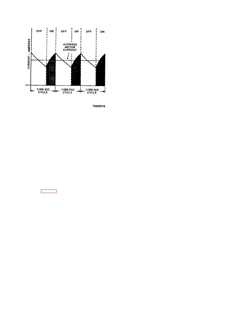
Figure 9-4. Control cycles.
closed, the control circuit module will energize. Current
flow is from the positive side of the battery through the
(2) To provide smooth motor operation, the on-
power fuse and F2 16 amp control fuse to terminal P5-8
off cycle of the system is kept very short. Cycle times in
of the contactor panel. Current flow continues from
the order of milliseconds are used. Mechanical switches
terminal P6-8 through S1 key switch, S2 seat switch,
cannot accomplish this fast
switching; however,
and terminal P2-7 of plug P2 on the static panel to
transistors offer very efficient high speed switching.
terminal P1-22 of the control circuit module. The current
(3) Transistors in the system are turned on and
path continues out of control circuit module terminal P1-
off to convert the steady power from the battery into
18 through the capacitor B- bus bar to the B-terminal of
pulses that are supplied to the drive motor at a rate of
the static panel, and from there back to the negative
300 pulses per second. The on time of the transistors
side of the battery.
can be varied from zero to maximum. This variable on
(2) With a forward direction selected, current
time controls the motor speed. At slow speeds the on
flows from the closed key switch (S1-2) through the
time is very short. Increasing the on time through the
directional switch to terminal P5-12 of the contactor
range increases the motor speed until at high speed the
panel. In the contactor panel, the path is from terminal
on time is the full duration of the cycle.
P5-12 through the normally closed reverse interlock
(4) The on time of the transistors in the power
contacts, the forward contactor coil, contactor panel
switch module (fig. 9-2) is varied by the speed control
terminal P5-6, and terminal P2-6 of plug P2 on the static
which causes the control circuit module to turn the
panel to terminal P1-6 of the control circuit module.
transistors on and off.
Note
(5) During the off time of the control circuit
The directional interlock contacts are physically
module, induced motor current is allowed to flow
mounted on the forward and reverse contactors
through the motor in the proper direction. This current
and are mechanically operated whenever the
flow is through the free wheeling diode. The armature
applicable contactor closes or opens. The
diode allows rapid reversals of the directional selector
forward interlock contacts are mounted on the
and prevents the motor from acting as series generator.
forward contactor and the reverse interlock
(6) The forward and reverse switch deter-
contacts are mounted on the reverse contactor.
mines the path of current flow through the motor field to
(3) The current path continues out terminal P1-
provide the desired directional travel.
18 of the control circuit module, through the B- terminal
c. Drive Power Circuit. Current flow during the on
of the static panel, and back to the negative side of the
time is from the positive side of the battery
battery.
(4) When the forward coil is de-energized,
9-6
|
|
Privacy Statement - Press Release - Copyright Information. - Contact Us |