 |
|||
|
|
|||
|
|
|||
| ||||||||||
|
|
 TM 10-3930-631-34
(2) Install spring (6, fig. 4-6) in body (8) and
remove front wheels, wheel cylinder, brake assembly
install a cup (5) and a piston (4) in each end.
and disassemble front wheel.
b. Inspection and Repair.
(3) Install boots (3). Boots must be properly
located in grooves in body.
(1) Refer to TM 10-3930-631-12 for F
(4) Install bleed screw (7) in body.
procedures on repair and replacement for brake shoes
e. Installation. Refer to TM 10-3930-631-12 and
(11, fig.
install wheel cylinder.
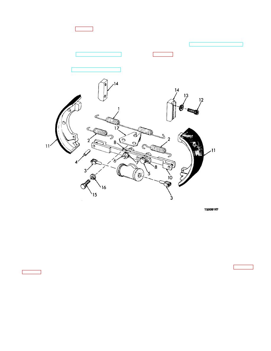
4-7. Brake Assembly and Brake Drum
a. Removal. Refer to TM 10-3930-631-12 and
1.
Upper spring
7. Lock washer
13.
Lock washer
2.
Lower spring
8. Nylon washer
14.
Wear plate
3.
Cylinder link
9. Slide
15.
Screw
4.
Pin
10. Adjuster assembly
16.
Lock washer
5.
Screw
11. Brake shoe
17.
Bracket
6.
Nut
12. Screw
Figure 4-7. Service brake, exploded view.
(2) Inspect and repair brake drum (part of wheel
(b) Inspect lining wear pattern (fig.
18, fig. 3-16) as follows:
Resurface or replace bell mouthed or barrel shaped
(a) Check inside diameter of brake drum at
drums. Scored drums should be resurfaced if scoring is
points 45 degrees apart.
Resurface drum if
over 0.010 inch (0.254 mm) deep. Resurface drums that
measurements differ more than 0.010 inch (0.254 mm).
are heat checked.
4-10
|
|
Privacy Statement - Press Release - Copyright Information. - Contact Us |