 |
|||
|
|
|||
|
|
|||
| ||||||||||
|
|
 TM 10-3930-631-12
4-51. Hydraulic Pump
a. Remove the floor and toe plates and drip pan to
gain access to hydraulic pump.
b. Check pump and motor for secure mounting.
Inspect pump and hose connections for
c.
evidence of leaks. Tighten connections if necessary.
Replace leaking or deteriorated hoses.
d. Install drip pan and floor and toe plates.
4-52. Hydraulic Control Valve
a. Remove cover from right side below seat to
gain access to control valve.
Move levers and check for freedom of
b.
operation in valve.
c. Check hose and tube connections to valve for
leaks. Inspect hoses for leakage and deterioration.
Replace hoses if necessary.
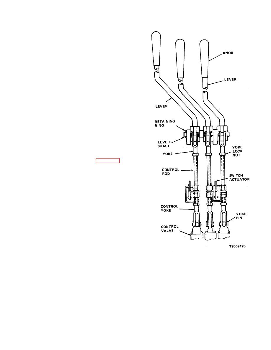
4-53. Control Levers and Linkage
control valve by linkages, actuate the lift, tilt and side
shift cylinders. Movement of the levers opens ports in
the valve to allow hydraulic pressure to flow to the
cylinders. Two switches normally open, are mounted on
brackets behind the control rods. When a control lever is
moved, the actuator contacts and closes the switch and
starts the hydraulic pump motor. Remove sheet metal
cover to gain access to linkage.
adjust linkage as follows:
Figure 4-36. Hydraulic valve linkage.
4-44
|
|
Privacy Statement - Press Release - Copyright Information. - Contact Us |