 |
|||
|
|
|||
|
Page Title:
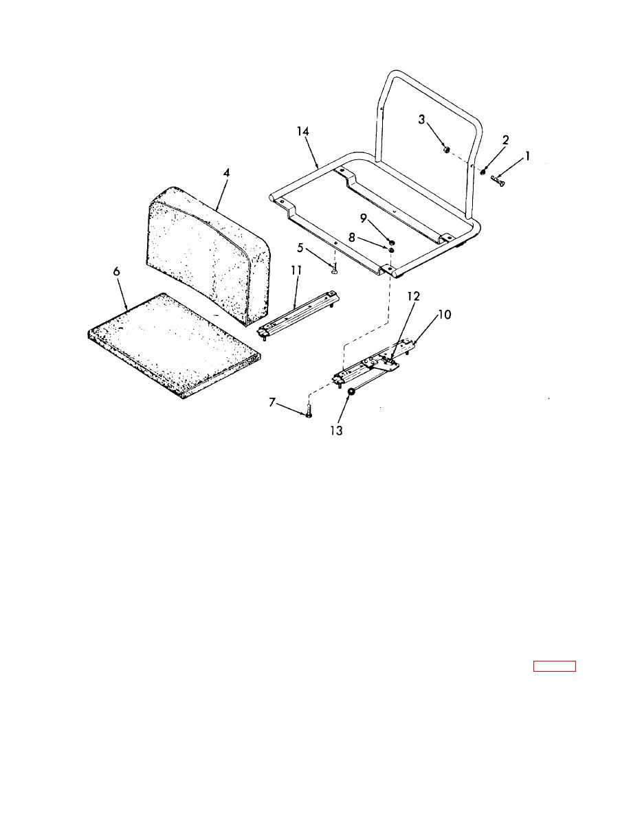
Figure 4-34. Seat assembly, exploded view. |
|
||
| ||||||||||
|
|
 TM 10-3930-631-12
1. Screw
2. Washer
3. Nut
4. Back cushion
5. Screw
6. Seat cushion
7. Screw
8. Washer
9. Nut
10. Adjustable slide
11. Slide
12. Spring
13. Knob
14. Seat frame
Figure 4-34. Seat assembly, exploded view.
c. Assembly.
(2) Remove screws (7), lock washers (8)
and nuts (9) and remove slides (10 and 11) from frame
(1) Install slides (10 and 11, fig. 4-34) on
(14).
frame (14) and secure with screws (7), lock washers (8)
(3) Check spring (12) for good condition.
and nuts (9).
4-41
|
|
Privacy Statement - Press Release - Copyright Information. - Contact Us |