 |
|||
|
|
|||
|
Page Title:
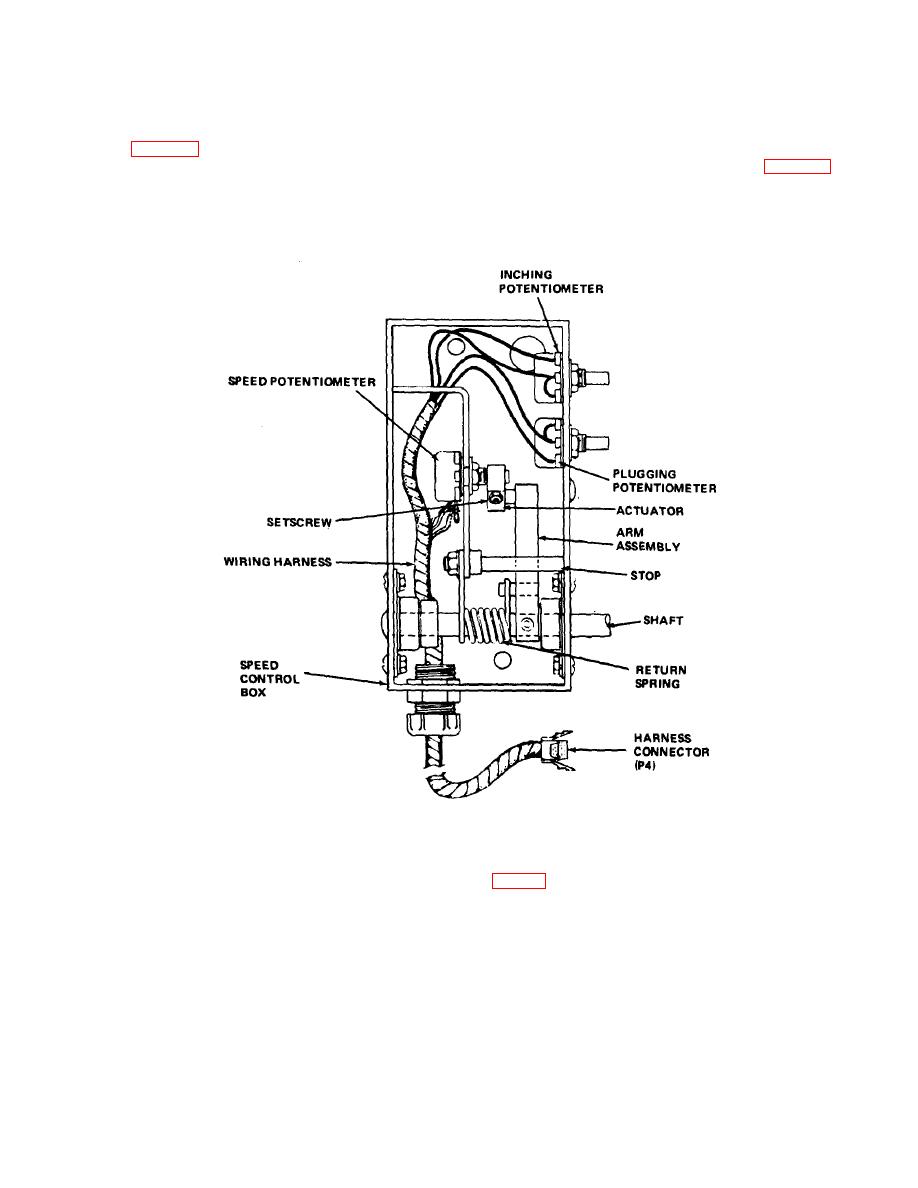
Figure 4-13. Accelerator control box, installed view. |
|
||
| ||||||||||
|
|
 TM 10-3930-631-12
c. Pump Motor Brushes. Remove the drip pan
d. Accelerator Control. This control is located on
and acid tray. Remove rear band from the motor.
the front part of the frame to the left of the steering
Brushes will appear through inspection hole in the field
column. Remove the cover from the box to gain access
yoke (A, fig. 4-12). Inspect brush condition and
to the components. Inspect components as follows:
commutator for wear and damage. Check spring for
(1) Check potentiometer (fig. 4-13) for
cracks, damage, and unserviceable conditions. Install
secure mounting and operation.
rear band to motor. Install drip pan and acid tray.
Figure 4-13. Accelerator control box, installed view.
(2) Check actuator and arm for proper
panel. To inspect the switch, remove cover from box
operation. Depress accelerator and observe operation of
speed potentiometer.
Install cover on box.
(3) Inspect return spring for cracks and
f. Harness Wiring. Inspect the wiring harnesses
damage. Operate accelerator and observe action of
for damage, broken wires, damaged insulation, loose
return spring.
terminals, and insecure mounting. Repair and tighten
e. Forward and Reverse Switch. The forward and
terminals. Tape or cover damaged insulation. Connect
reverse switch is mounted in a box below the instrument
broken wires, if possible. Tighten mounting clamps and
4-18
|
|
Privacy Statement - Press Release - Copyright Information. - Contact Us |