 |
|||
|
|
|||
|
Page Title:
Section III. REPAIR PARTS, SPECIAL TOOLS, AND EQUIPMENT |
|
||
| ||||||||||
|
|
 TM 10-3930-631-12
c. Battery.
(1) Open battery compartment and remove
CAUTION
side panels.
Do not reverse polarity of battery cables.
(2) Using a hoist of sufficient capacity, lift
(4) Service and charge battery as described
battery into compartment.
(3) Connect battery receptacle as shown in
Section II. MOVEMENT TO A NEW WORKSITE
another carrier, refer to figure 4-1 and remove the forks.
4-3. Dismantling for Movement
4-4. Reinstallation after Movement
The only component that may require dismantling
for movement is the forks. If necessary to conserve
If forks were removed to transport the lift truck,
space when transporting the lift truck by means of
refer to figure 4-1 and install the forks on the carriage.
Section III. REPAIR PARTS, SPECIAL TOOLS, AND EQUIPMENT
perform organizational maintenance of the fork lift truck.
4-5. Tools and Equipment
4-7. Maintenance Repair Parts
Tools, equipment and repair parts issued with or
authorized for the fork lift truck are listed in the basic
Repair parts and equipment are listed and
issue items list, appendix C.
illustrated in the repair parts and special tools list (TM
10-3930-631-20P) for the fork lift truck.
4-6. Special Tools and Equipment
No special tools and equipment are required to
Section IV. LUBRICATION INSTRUCTIONS
4-8. General
These paragraphs contain lubrication instructions
which are supplemental to and not specifically covered in
the lubrication order.
4-9. Hydraulic Filter
a. Replacement of the filter element is required at
regular intervals.
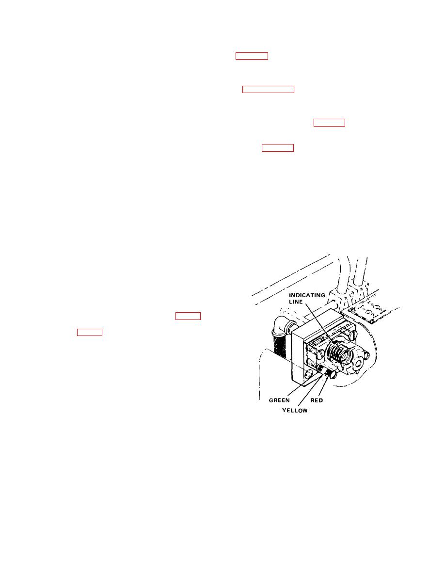
b. A hydraulic filter element indicator (fig. 4-2) is
located to the right of the control valve handles. The
indicating line (fig. 4-2) should be in line with the green
band. This indicates filter element is operating properly.
If indicating line is in line with yellow band element is
becoming contaminated and should be changed at
earliest convenience.
When white indicating line
reaches any portion of red band, change filter element at
once.
Figure 4-2. Hydraulic filter element indicator,
installed view.
4-3
|
|
Privacy Statement - Press Release - Copyright Information. - Contact Us |
