 |
|||
|
|
|||
|
|
|||
| ||||||||||
|
|
 TM 10-3930-628-12
the contactor box. Hose assemblies lead from the
control valve to the filter and from the filter to the
reservoir.
b. Service. Service of the filter consists of
replacing the filter element. Remove sheet metal cover
at right side below seat. Refer to figure 4-31 and service
the filter as follows:
(1) Place a suitable container or rags below
filter to catch oil as element is removed.
(2) Unscrew body (10) from filter head (7).
Remove element (8) from body.
(3) Clean head and interior of body and in-
spect for nicks and defects.
(4) Inspect packing (9) in groove in body.
Replace if necessary.
(5) Install new element (8) in body and new
packing (9) if required.
(6) Install body (10) in filter head (7) and
tighten snugly.
(7) Operate truck hydraulic system and check
filter for leaks. Check level of oil in reservoir and add oil
to bring to full mark on gage.
c
Removal. Remove sheet metal cover.
Refer to figure 4-32 and remove oil filter as follows:
(1) Place a suitable container below filter to
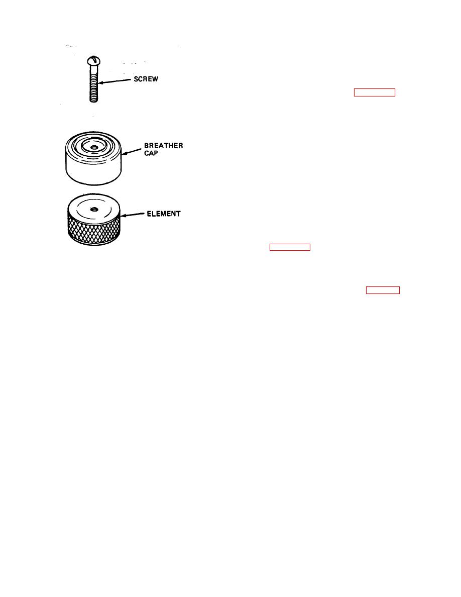
Figure 1-.30. Hydraulic reservoir breather. exploded
catch oil. Loosen hose clamps and disconnect hose
view.
assemblies from both sides of head. Plug hoses to
4-51. Hydraulic Oil Filter
prevent entrance of foreign material.
a
General. The micron-type hydraulic oil filter
(2) Remove two screws (4, fig. 4-31) and lock
is mounted above the control valve on the right side of
washers (5) securing filter head (7) to bracket (3) and
remove complete filter assembly.
(3) Remove two elbows from filter head.
KEY to fig. 4-31:
1. Nut
2. Lock washer
3. Bracket
4. Screw
5. Lock washer
6. Screw
7. Head
8. Filter element
9. Packing
10. Body
4-30
|
|
Privacy Statement - Press Release - Copyright Information. - Contact Us |