 |
|||
|
|
|||
|
Page Title:
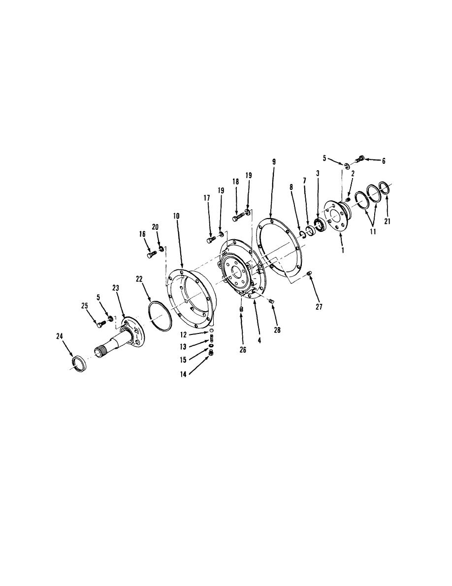
Figure 7-6. Oil pump and front case. |
|
||
| ||||||||||
|
|
 i. Remove counter shaft gear (25) and shaft (15) in
(3) Remove cap screw (42) and lock washer (43)
holding bearing retainer.
the following manner:
(4) Tap end of reverse drive shaft (31) and while
(1) Remove nuts (24), lock washer (23) bearing
holding reverse gear (36) pull shaft out thru opening in
roller (19) and cup (3). Take shims (20, 21 and 22) from
housing.
shaft and remove spacer (18).
h. Remove idler gear (26) and shaft (28) in the
(2) Remove counter shaft gear by tapping lightly
on the forward end, while holding the output gear
following manner:
through the valve block opening.
(1) Tap small end of idler shaft and remove
j. Remove the strainer element (7) by removing
retainer (30).
(2) Remove idler gear and bearings (27) through
retaining cap screws (9) and washers (10) inside of
the valve block opening.
case.
ME10-3930-627-34-/7-6
1.
Front bearing retainer
11.
Sealing ring
20.
Lock washer
2.
Plug
12.
3/8 in. steel ball
21.
Sealing ring
3.
Bearing
13.
Converter valve spring
22.
Pump gasket
4.
Adapter
14.
Spring seat
23.
Pump
5.
Lock washer
15.
Flat washer
24.
Oil seal
6.
Screw
16.
Screw
25.
Screw
7.
Bearing spacer
17.
Screw
26.
1/8 in. pipe plug
8.
Drive gear snap ring
18.
Screw
27.
1/4 in. pipe plug
9.
Case gasket
19.
Lock washer
28.
3/8 in pipe plug
10.
Converter housing
Figure 7-6. Oil pump and front case.
7-8
|
|
Privacy Statement - Press Release - Copyright Information. - Contact Us |