 |
|||
|
|
|||
|
Page Title:
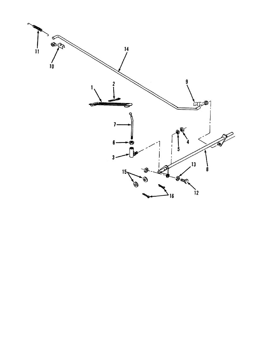
Figure 4-10. Accelerator linkage. |
|
||
| ||||||||||
|
|
 TM 10-3930-627-12
1.
Pedal
9. Clip
2.
Cotter pin
10. Clip
3.
Ball joint
11. Return spring
4.
Nut
12. Pedal stop screw
5.
Lock washer
13. Jam nut
6.
Jam nut
14. Throttle rod
7.
Rod
15. Flat washer
8.
Cross shaft
16. Cotter pin
Figure 4-10. Accelerator linkage.
b.
Assembly and Installation.
Reverse
(2) Hold throttle rod (14) forward so pedal
procedure in a above.
stop screw (12) is held against stop.
(3) Adjust pedal stop screw so carburetor
c. Accelerator Pedal and Linkage Adjustment.
end of throttle rod freely enters hole in carburetor throttle
(1)
With floor plate removed, hold
lever. Install clip (10), floor plate and pedal.
carburetor throttle valve fully open.
4-15
|
|
Privacy Statement - Press Release - Copyright Information. - Contact Us |