 |
|||
|
|
|||
|
|
|||
| ||||||||||
|
|
 f. Bearing Adjustment.
(1) Using an inside spanning tool, locate the
narrowest point in the web of the inner mast
assembly. Set an outside spanning tool to match the
inside spanning tool. Lock tools in position.
(2) Using the outside spanning tool, span the
carriage bearings at their maximum camber points.
Add shims as necessary to produce a maximum
clearance of 0.015 inch.
(3) Place a straightedge against the stud
centerline to all three bearings on both sides of the
carriage. N o g a p s h o u l d a p p e a r b e t w e e n t h e
bearings and the straightedge.
6-4. Forks
a. Removal. Refer to TM 10-3930-624-12 for
the removal procedure.
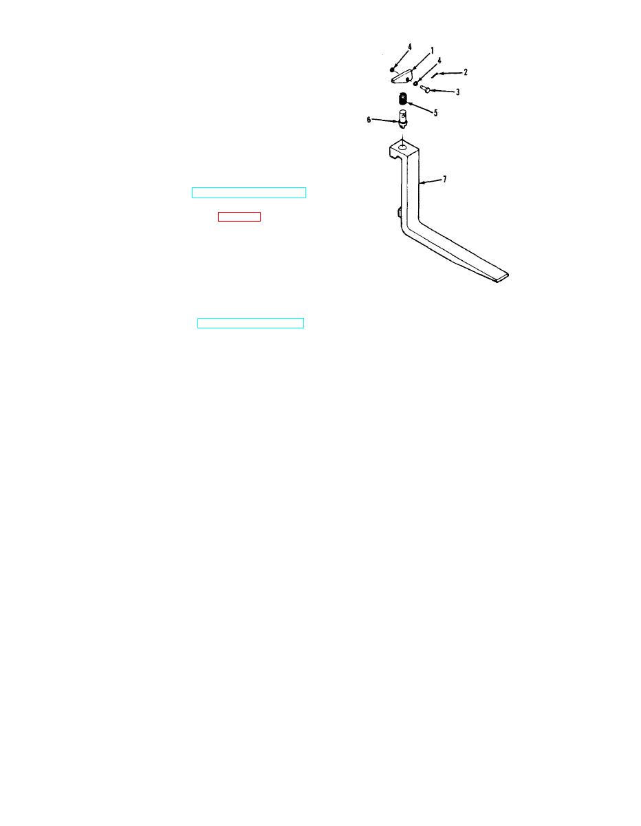
h. Inspection and Repair. (fig. 6-3.)
(1) Inspect the latch (1), clevis pin (3), spring
(5), and lock pin (6) for signs of wear or damage. If
any of these parts are worn or damaged they must
be replaced as a unit.
(2) If the fork (7) is damaged, replace as
authorized.
ME 3930-624-34/6-3
c. Installation. Refer to TM 10-3930-624-12 for
5. Spring
the installation procedure.
1.
Latch
2.
Cotter pin
6. Lock pin
3.
Clevis pin
7. Fork
4.
Washer
Figure 6-3. Fork and locking mechanism.
Section II. REPAIR OF THE FRAME
6-5. General
broken welds, distortion or other damage. Repair
cracks in the frame by welding. Replace a badly
The frame of the truck is of the heavy duty, in-
dam aged frame.
dustrial type, designed for long service life with
c. Inspect all frame hardware and threaded holes
minimum maintenance.
for thread damage. Use an appropriate tap or die to
6-6. Repair
chase the threads if necessary. If hardware cannot
a. CIean all parts using any applicable method.
be repaired, replace the part.
b. Inspect the frame for cracks, cracked or
6-5
|
|
Privacy Statement - Press Release - Copyright Information. - Contact Us |