 |
|||
|
|
|||
|
|
|||
| ||||||||||
|
|
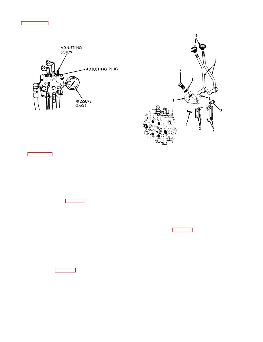 (3) Remove the plug from the front end of the
(3) Remove capscrew (5) and washer (6).
valve body adjacent to the high pressure inlet port.
Remove lever (7) which is keyed to the control
Connect an oil pressure gage to the port as shown in
handles (9). and remove the control handles.
approximately 3000 psi.
ME 3500-624-34/5-11
Figure 5-11. Adjusting relief valves.
(4) Start the engine and run at 600 rpm.
(5) Remove the washer from the body nut.
Place a nut driver over the poppet adjusting screw
and engage the slots in the adjusting plug as shown
in figure 5-11.
ME 3930-624-34/5-12
(6) Run the tilt cylinder to the end of its stroke
and hold it in this position long enough for pressure
1.
Cotter pin
6. Washer
to show on the gage. Turn the adjusting plug in or
7. Lever
2.
Pin
nut until a pressure reading of 150 to 250 psi above
8. Key
3.
Link
the required relief valve setting of 1950 psi is
9. Handle
4.
Link
reached.
5.
Capscrew
10. Knob
(7) Taking care not to disturb the position of
Figure 5-12. Control levers.
the adjusting plug, loosen the pilot valve adjusting
screw several turns (fig. 5-11).
b. Cleaning and Inspection.
(8) Install the larger of the two washers and
(1) Clean all metallic parts in cleaning
the locknut. Do not tighten the locknut.
solvent.
(9) With a screwdriver in the slot of the ad-
(2) Inspect all parts for cracks, distortion and
justing screw, accelerate the engine to a high rpm
excessive wear. Replace as necessary.
and actuate the tilt cylinder to the end of its stroke.
Turn the adjusting screw in or out until a pressure
(1) Slide control handles (9) through truck
reading of 1950 psi 50 psi is obtained on the
frame. Install key (8) in keyway on control handle
gage.
shaft.
(10) While holding the adjusting screw in
(2) Install control lever (7). washer (6) and
position. install and tighten the locknut. Install the
capscrew (5) on control handle shaft. Tighten
second washer and cap nut.
capscrew securely.
5-7. Control Levers and Linkage
(3) Install links (3 and 4) to the plungers of
valve and to control lever (7). Secure links with pin
(1) Remove four capscrews, washers, and nuts
(2) and cotter pin (1).
securing the cowl to the truck frame. Remove the
5-8. Tilt Cylinder
cowl to obtain access to the control valve and
a. Removal.
linkage.
(1) Place the mast in forward position. Hold
(2) Remove cotter pin (1) and pin (2) securing
the mast in position with a chain hoist.
links (3 and 4) and remove the links.
5-12
|
|
Privacy Statement - Press Release - Copyright Information. - Contact Us |
