 |
|||
|
|
|||
|
Page Title:
Cleaning, Inspection and Repair. |
|
||
| ||||||||||
|
|
 (8) Remove the bushing (9) if it is excessively
or unevenly worn.
(9) Remove the rings (10 and 11) if they must
be replaced.
b. Cleaning, Inspection and Repair.
Caution: Do not use cleaning solvents
containing chemicals which will react with
aluminum alloy.
(1) Clean all parts with a cleaning solvent and
dry with compressed air.
(2) Use the following procedure to check for
piston wear.
(a) Inspect the piston skirt for score marks
or other indications of improper piston clearance.
Inspect the inside of the piston for cracks. Replace
any piston that is scored or cracked.
(b) Check the piston for wear by inserting it
into its respective cylinder sleeve and measuring the
clearance between the piston and the sleeve. Make
sure that the piston is inserted into the sleeve far
enough so the measurement is taken in the area of
the piston ring travel. The specified clearance is
f r o m 0 . 0 0 2 3 - 0 . 0 0 4 8 i n c h , measured at the
bottom of the piston skirt and at right angles to the
piston pin. The piston skirt diameter of a new
piston is 3.4365-3.4385 inches. measured at the
right angles to the piston pin. The inside diameter
of a new cylinder sleeve is 3.4379-3.4385 inches.
T h e piston or cylinder sleeve, or both, must be
replaced if the clearance exceeds 0.008 inch.
(c) If the piston is to be replaced, new rings
must be used.
(3) Use the following procedure to inspect the
piston rings.
(a) Select the rings to be installed on each
piston and insert them one at a time into the
cylinder sleeve in which they are to operate. Use a
piston to push the ring squarely into the cylinder
sleeve so that it is parallel with the top of the
cylinder block. Push the ring far enough down into
the bore of the cylinder sleeve to be on the ring
travel area.
(b) Measure the ring gap with a feeler gage.
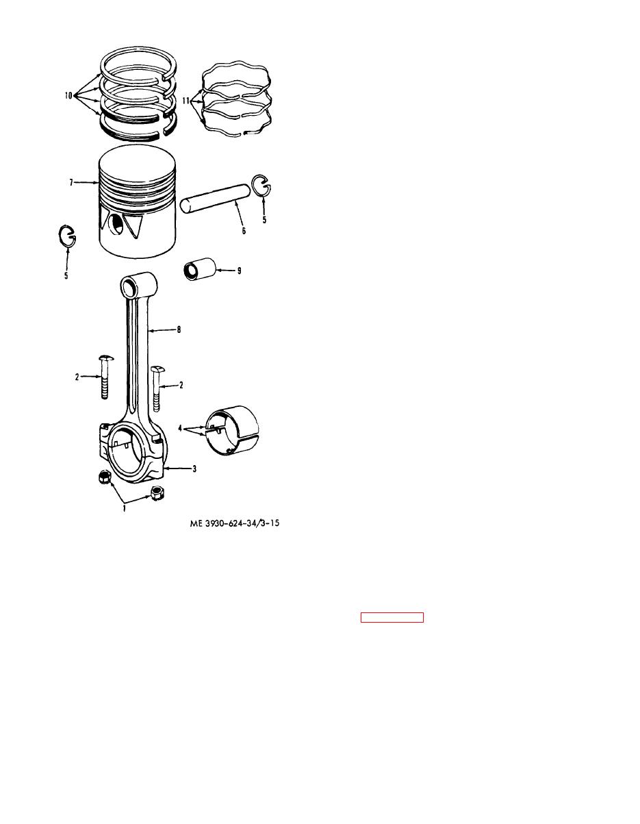
1. Nut
7. Piston
The ring gap specification for all rings is 0.011 inch
2. Capscrew
8. Connecting rod
3. Bearing cap
minimum. If necessary, file the ring ends with a
9. Bushing
4. Liner
10. Ring
fine cut file to obtain the correct clearance.
5. Retaining ring
11. Ring
(c) Measure the ring to groove clearance
6. Pin
(top of the ring to top of the groove in the piston).
Figure 3-15. Piston and connecting rod.
Refer to figure 3-16. Specified clearances are as
(6) Remove the liners (4) if they are to be
follows: top-compression 0.002-0.004 inch,
replaced.
second-compression 0.0015-0.0035 inch. third-oil
(7) Remove the piston pin retaining rings (5).
control 0.0015-0.0035 inch, and fourth-oil control
Drive out the pin (6) using a wood block or brass
0.001-0.003 inch.
drift.
3-18
|
|
Privacy Statement - Press Release - Copyright Information. - Contact Us |
