 |
|||
|
|
|||
|
Page Title:
Install the wear sleeve (4) as follows: |
|
||
| ||||||||||
|
|
 the crankshaft. If the surface is not smooth and true
they flywheel may wobble. This will result in
improper torque converter operation and engine
vibration.
(1) If the ring gear (5) was removed, install as
follows:
(Caution: Do not heat the ring gear to a
bright red as heat-treatment will be destroyed.
(a) Heat the ring gear uniformly to ap-
proximateIy) 400F (red heat visible in the dark).
Keep the flywheel at room temperature.
(b) Start the ring gear on the flywheel (3) so
the chamfered ends of the teeth are facing the
cylinder block. These ends of the teeth engage with
the drive pinion of the starter motor.
(c) Drive the ring gear down tight against
the shoulder of the flywheel. Allow the ring gear to
cool slowly. do not cool with water.
(2) Install the wear sleeve (4) as follows:
(a) Position the wear sleeve so its beveled
edge is in the same direction as the beveled edge of
the flywheel.
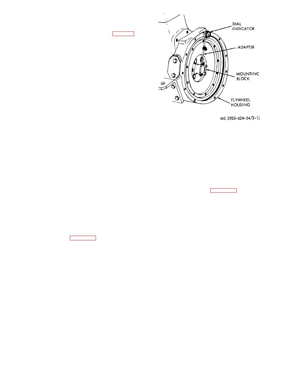
Figure 3-12. Checking flywheel housing runout.
(b) Do not use any lubricant or sealer
between the wear sleeve and flywheel flange. Metal
(8) If a new flywheel (3) is to be installed,
to metal contact between the sleeve and flywheel
compare the timing marks of the old and new
flange is required for adequate heat flow to prevent
flywheels.
overheating and burning of the oil seal.
(9) Install the flywheel by reversing the
(c) Do not heat the wear sleeve before in-
removal procedure. The flywheel can be installed in
stalling. Press on when the wear sleeve and flywheel
only one position because of the offset capscrew
are at approximately the same temperature.
hole.
(3) Install a new outer oil seat (8) and a new
(10) Attach a dial indicator and check the
rear oil seal (7) on the flywheel housing.
flywheel runout. Refer to figure 3-13. Runout must
(4) Reassemble the remaining flywheel
not exceed 0.005 inch.
assembly components.
(5) Ensure that the mating surfaces of the
flywheel housing and the cylinder block are clean
and smooth
(6) Install the flywheel housing in the reverse
order of removal.
(7) Using a dial indicator. check the housing
runout. Refer to figure 3-12. Total runout must not
exceed 0.010 inch.
3-15
|
|
Privacy Statement - Press Release - Copyright Information. - Contact Us |