 |
|||
|
|
|||
|
|
|||
| ||||||||||
|
|
 (4) Inspect the bearing cones for pitting,
c. Installation. Install the wheel and tire assembly
scoring, wear, cracked cages, and for rough or binding
by reversing removal procedure. Refer to para 4-56 for
operation. Replace damaged bearings.
torquing of wheel bearings.
(5) Inspect the bearing cups for scoring,
scratches, nicks, and other damage. If damaged, drive
4-56. Wheel Bearings
the cups from the wheel hub using a soft drift.
a. Removal and Disassembly
Press in new bearing cups, taking care not to damage
Warning: Block the truck before attempting
the cups or hub.
to remove the wheels.
(1) To raise the front end of the truck for
the interior of the hub with the lubricant recommended
wheel and tire replacement, tilt the mast back as far as
by the lubrication order. Take care to prevent dirt or grit
possible and install a wooden block under the mast
from contaminating the grease.
assembly. Tilt the mast forward to raise the front of the
During reassembly, pack the ring gear of the drive
truck. To raise the rear wheels for wheel and tire
wheels with grease.
replacement, use a jack or hoist. Place blocking under
d. Reassembly.
the frame.
(1) Reassemble the bearings and hub on the
(2) Remove the wheel and tire assembly as
spindle or steering knuckle in the reverse order of
directed in paragraph 4-55.
disassembly.
(3) Remove inner wheel bearing (9, fig. 4-53).
(2) Tighten drive wheel bearing nuts as
b. Cleaning and Inspection.
follows. Using a torque wrench, tighten nuts (5, fig. 4-
(1) Clean the bearing cones by flushing up
and down in a cleaning solvent. If necessary, tap the
torque is applied turn wheel six times in each direction,
large side of the bearing against a soft wooden block to
then back nut off 300 minimum to 60 maximum so
dislodge solidified grease. Dry the bearings with clean,
cotter pin can be installed. While tightening the steer
dry compressed air. Direct the stream of air at the
wheel nut, rotate the wheel six times in each direction
bearing so that the rollers and cage will not spin. Dip
while torquing nut to 50 ft. lbs. Back nut off to 0 ft.-lbs.,
the bearings in light oil immediately after cleaning.
then retorque to 25 ft. lbs. while turning the wheel.
(2) Clean the hub and spindle (10) with a
Finally back nut off 30 o minimum to 60 maximum and
cloth dampened with cleaning solvent.
install the cotter pin.
(3) For the drive wheels, clean the ring gear
(3) Remove the blocking and lower the truck
and pinion with a cleaning solvent and dry with
to the ground.
compressed air.
Section XVI. MAINTENANCE OF THE STEERING SYSTEM
4-57. General
The rear wheels are used to steer the truck. Steering is
done by' a steering handwheel through the steering
valve, power steering cylinder, and the steer axle. The
steer axle is located beneath the engine at the rear of
the truck. The steering valve is mounted on the chassis
in front of the operator. Through the power steering
cylinder and pivot arm, the operator can turn the steer
wheels to control the direction of the truck.
4-58. Tie Rods
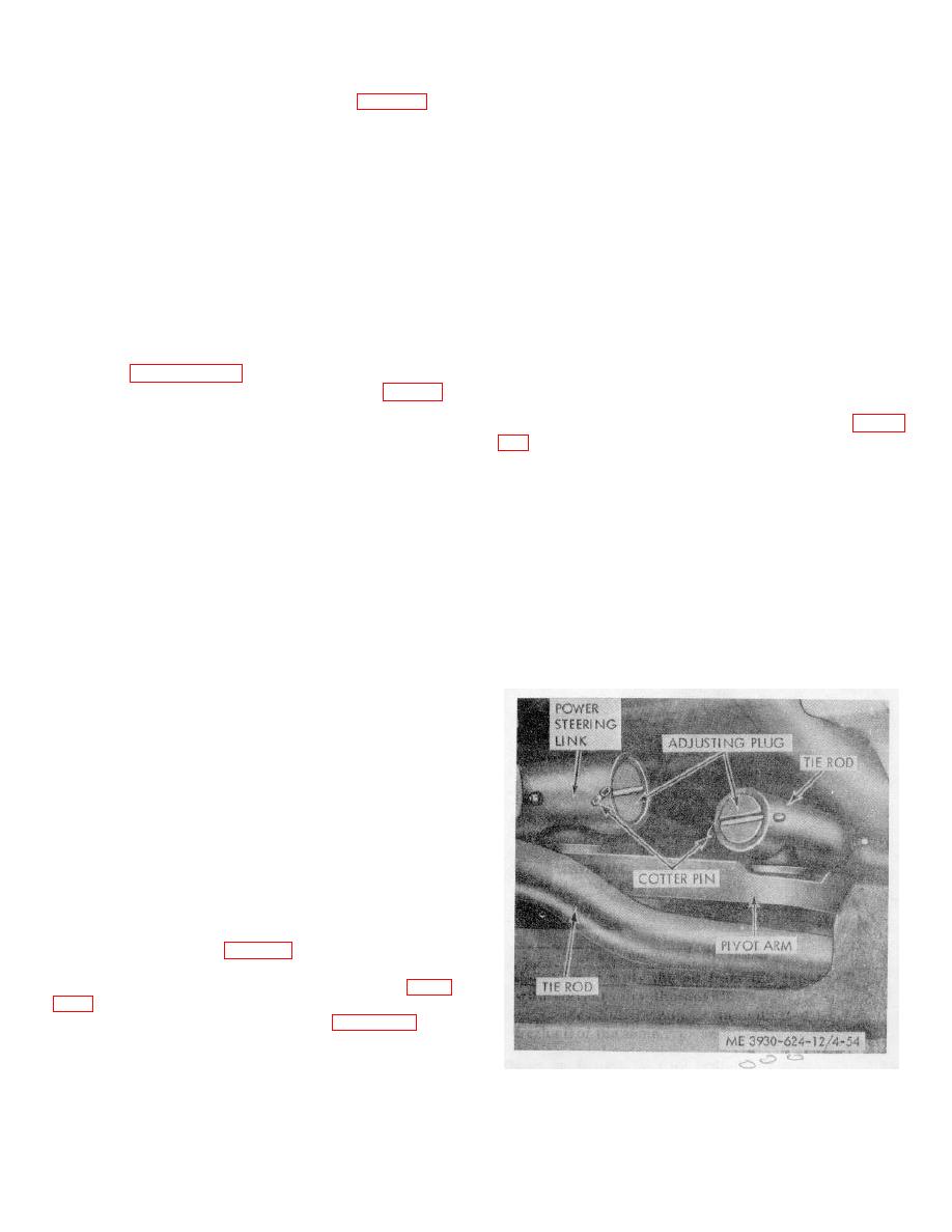
a. Removal and Disassembly.
(1) Remove the cotter pin and loosen the
adjusting plug in the end of the tie rod. Remove the tie
rod from the pivot arm. (fig. 4-54.)
(2) Remove the cotter pin nut and washer
from the tie rod at the steering knuckle. Refer to figure
(3) Disassemble as shown in figure 4-56.
Figure 4-54. Tie rod removal (pivot arm end).
4-45
|
|
Privacy Statement - Press Release - Copyright Information. - Contact Us |