 |
|||
|
|
|||
|
Page Title:
Section XIII. MAINTENANCE OF SHAFTS AND AXLES |
|
||
| ||||||||||
|
|
 Section XIII. MAINTENANCE OF SHAFTS AND AXLES
b. Servicing. To pack the universal joints with
4-46. Propeller Shafts
lubricant proceed with the following steps.
a. Removal.
Caution: All parts of the universal joint and
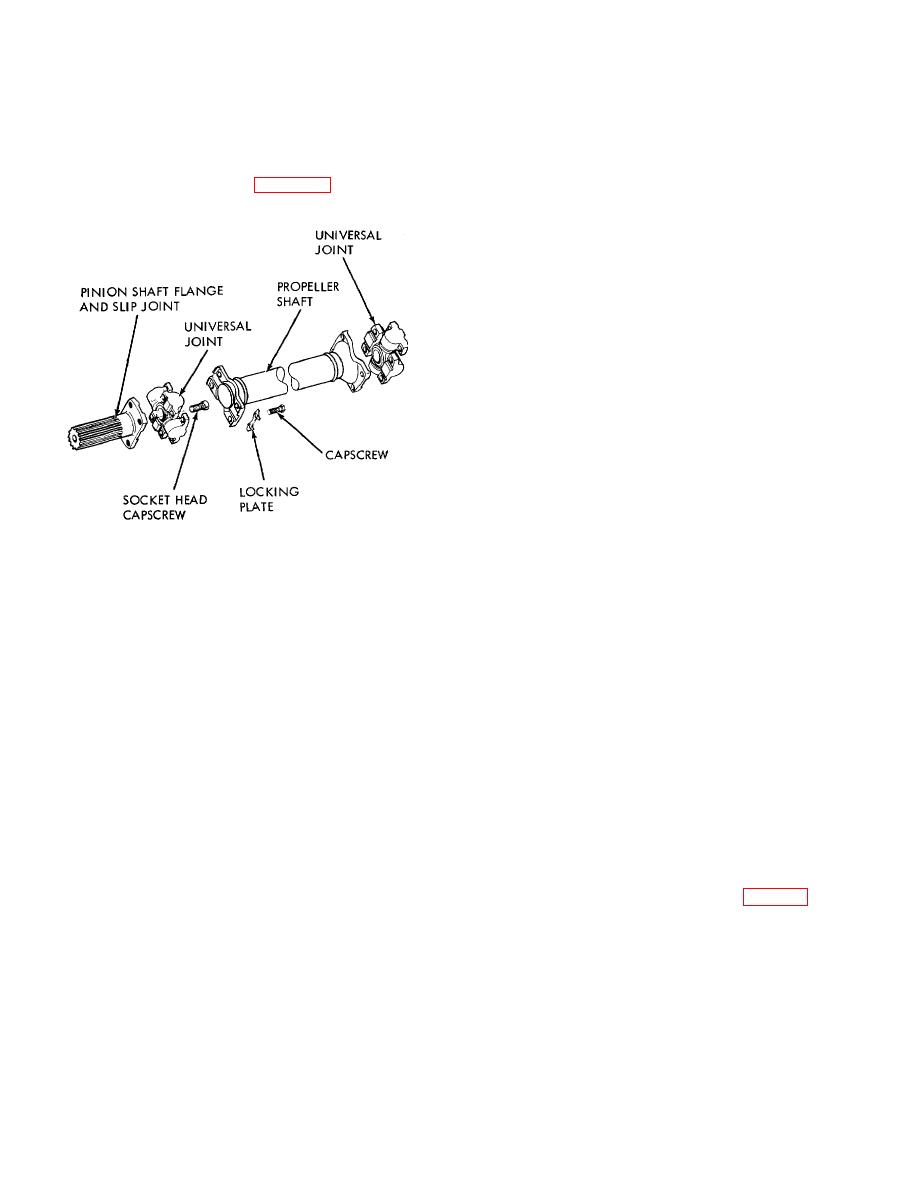
(1) Remove wires and socket head
capscrews holding universal joints to the pinion shaft
propeller shaft assembly should be cleaned
flange and slip joint. Refer to figure 4-45.
thoroughly before assembly. Abrasives are very
harmful to this assembly.
(1) After the universal joints have been
removed from the truck, break connecting plate tying
the trunnion bearings together. These connecting plates
need not be replaced.
(2) Inspect all bearings and surfaces for
irregularities and replace damaged parts.
(3) Pack the trunnion bearings thoroughly
with a high melting point wheel bearing or universal joint
grease.
Make sure grease fully covers bearing
surfaces.
(4) To reassemble, reverse the removal
procedure. It is recommended that the capscrew locking
plates be replaced.
c. Installation. To install the drive shaft, reverse
the removal procedure.
4-47. Drive Axle Assembly
The drive axle and bearings should be
ME 3930-624-12/4-45
lubricated at periodic intervals in accordance with the
current lubrication order. All parts should be checked
Figure 4-45. Universal joint and propeller shaft.
for possible damage and excessive wear.
(2) Slide the output shaft slip joint into the
4-48. Differential
transmission and remove the propeller shaft assembly.
The oil level in the differential housing should
(3) Bend back clips on a capscrew locking
be checked periodically and changed as specified in the
plates and remove both universal joints.
current lubrication order.
(4) If necessary remove slip joint from
transmission.
Section XIV. MAINTENANCE OF THE BRAKES
of the drive axle, and the shoe assemblies are mounted
4-49. General
on the backing plate.
The parking brake is a dual shoe mechanical
brake, mounted on the drive shaft, and can be used
either as a parking brake or an emergency brake. The
4-50. Parking Brake
brake shoes are actuated through a cable by an
a. Removal.
adjustable over-center type lever mounted on the left
(1) Remove the floor plate.
hand cowl panel. A service brake is mounted on each
(2) Remove the clevis pin from the yoke and
of the drive wheels. The service brakes are operated by
remove the yoke from the brake lever (fig. 4-46).
hydraulic pressure. The brake drum rotates on the end
4-40
|
|
Privacy Statement - Press Release - Copyright Information. - Contact Us |