 |
|||
|
|
|||
|
|
|||
| ||||||||||
|
|
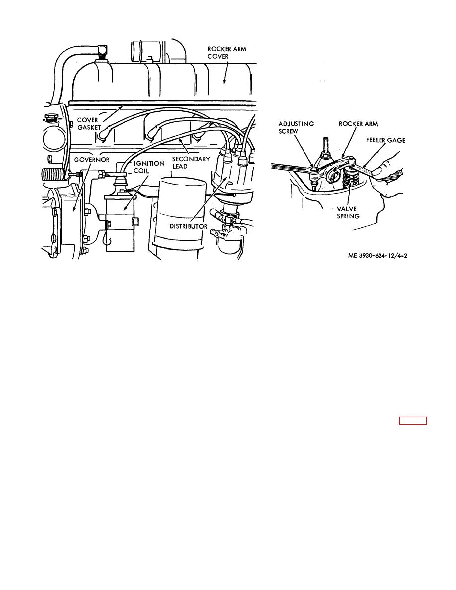
 Figure 4-2. Valve clearance adjustment.
and valve stem. If clearance is correct, a slight drag will
(5) Repeat above steps on the valves for the
be felt, followed by a momentary tightening which
other cylinders. Make sure the engine is cranked so
prevents movement of the feeler gage.
valves are closed and push rods are at lowest position
on cam lobes.
(9) Check all valves in the same manner as
outlined in step 8. Install the rocker arm cover and a
(6) Connect high tension wire to ignition coil and
new gasket.
start the engine.
(7) Operate engine until it reaches a normal
4-16.
Crankcase Ventilation
operating temperature of 1650 F and then stop engine.
Thoroughly clean rocker arm cover and surrounding
a. Replacement.
area.
(8) When the engine is hot and idling, slowly
(1) Remove screw (11), washer (12), and clamp
move a 0.010 inch feeler gage for the intake valve, and
(13) securing breather tube (5) to engine block (fig. 4-3).
a 0.012 for the exhaust valve, between the rocker arm
4-10
|
|
Privacy Statement - Press Release - Copyright Information. - Contact Us |