 |
|||
|
|
|||
|
Page Title:
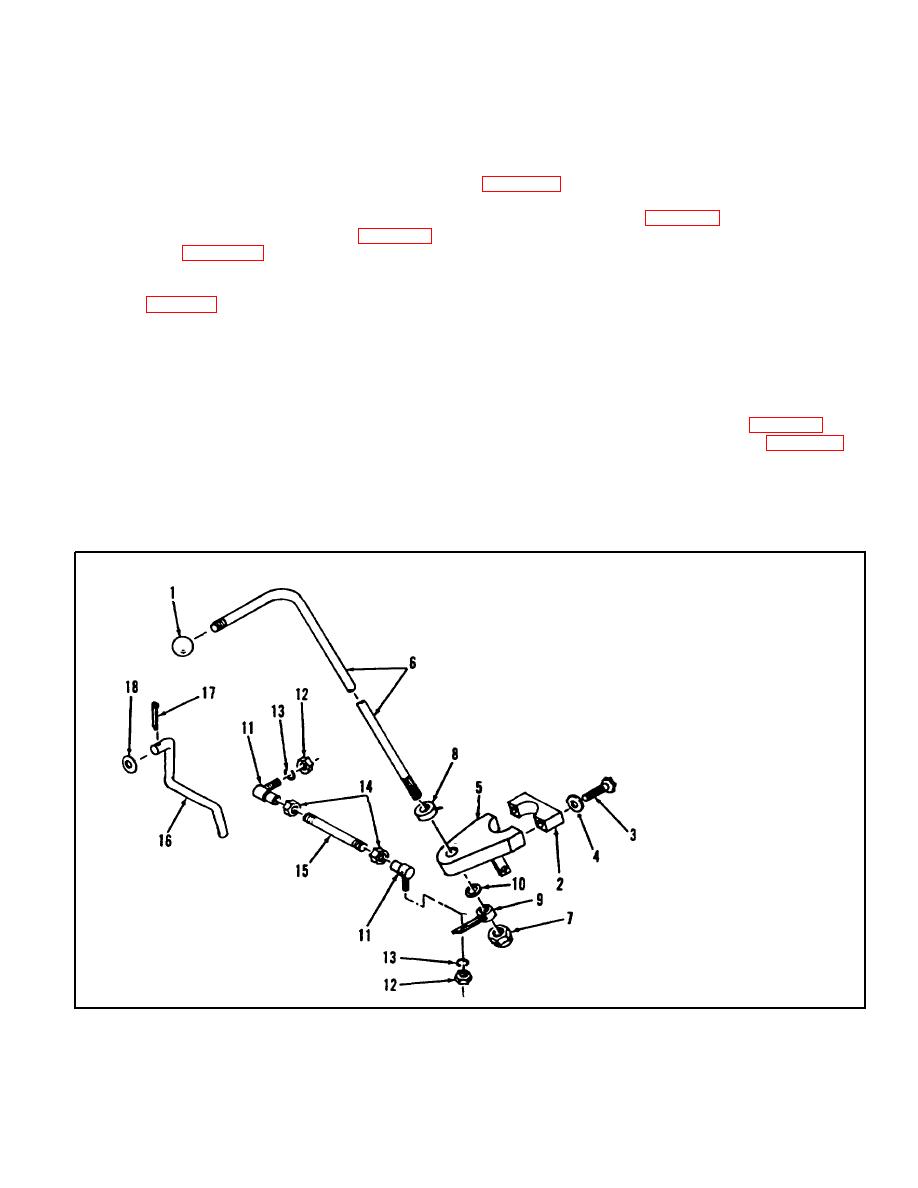
Figure 7-8. Transmission Directional Control Lever, Exploded View |
|
||
| ||||||||||
|
|
 TM 10-3930-623-34
3. Assemble inching adjustment screw (36) and nut
(37) to inching valve slide.
5. Assemble ball joints (11), and rod (15). Install
between shift lever collar (9) and bellcrank lever (31,
7-77.
DIRECTION AND INCHING
6. Position control valve slide in neutral detent
CONTROL INSTALLATION.
position. Adjust rod (15, figure 7-8) so knob end of lever
1. Assemble and install inching rod (16, figure 7-8)
(6) points directly to side of truck. Rotate shift lever and
and rod guide (19, figure 4-11) on transmission control
check operation of linkage in forward and reverse
valve.
positions.
2. Connect inching rod to the brake pedal with
7. Install knob (1).
cotter pin (17, figure 7-8) and washer (18).
3. Assemble pointer collar (8), bearing bracket (5)
7-78.
UPRIGHTS, CARRIAGE AND FORK
and shift lever (6). Install bracket under one steering
ASSEMBLY INSTALLATION.
column clamp screw and clamp to steering column with
cap (2).
1. Raise assembly with a hoist, and align mounts
4. Slide lever (6) through lower weldment and
on outer upright; with journals of drive axle. Install
assemble collar (10) and splined collar (9). Assemble
bearing caps.
locknut (7).
2. Reconnect wiring to spotlight (1, figure 4-1).
3. Connect tilt cylinder (79 and 80, figure 4-2) to
NOTE
uprights by installing pins (32) and screws (33).
4. Connect hydraulic hose at hoist cylinder fitting.
Lever arm on collar (9) must align
with knob end of shifter shaft (6). If
not remove and remate splines to
correct.
1.
Shift Lever Ball
2.
Bearing Cap
3.
Screw
4.
Lock Washer
5.
Lever Bearing Bracket
6.
Shift Lever
7.
Nut
8.
Pointer Collar
9.
Washer
10.
Lower Lever Collar
11.
BallJoint
12.
Nut
13.
Lock Washer
14.
Nut
15.
Shift Rod
16.
Inching Control Rod
17.
Cotter Pin
18.
Washer
Figure 7-8. Transmission Directional Control Lever, Exploded View
7-19
|
|
Privacy Statement - Press Release - Copyright Information. - Contact Us |