 |
|||
|
|
|||
|
Page Title:
REDUCTION GEAR AXLE END ASSEMBLY. |
|
||
| ||||||||||
|
|
 TM 10-3930-623-34
gear (24). Assemble washer (27) and nut (26). Torque
NOTE
nut until preload on bearings is 0.000 to 0.003 inch tight.
Insert new cotter pin (25).
Do not change total thickness of
gaskets (62 and 63) used; merely
6. Assemble reduction gear axle end to differential
change them from one side to the
section of the axle with gasket (48) screws (22) and
other as needed, so the differential
washers (23).
bearing preload will not be changed.
6. If marks in red lead compare with those in view
7. Assemble brake lines and fittings, guard and
B, figure 6-9, reverse adjustment procedure given in step
parking brake lever (2).
5 above. Repeat steps 1 through 4 above to check
results of adjustment.
6-65. STEERING GEAR REPAIR AND ASSEMBLY.
Complete disassembly of the
6-64. REDUCTION GEAR AXLE END ASSEMBLY.
6-66.
GENERAL.
steering gear at one time is not an overhaul operation.
1. Press bearing cups (29 and 34, figure 4-12) into
The instructions in following paragraphs present
reduction gear case (47).
complete information necessary to correct any
malfunction of the gear.
Before beginning repairs,
2. Assemble brake drum (35) to final axle shaft
diagnose the probable cause of the malfunction by
(30)
referring to the troubleshooting chart for the steering
gear (figure 7-11). Limit disassembly to necessary
with screw (31) and gasket (32). Press seal (36)
operations.
into brake drum. Assemble bearing cone and roller (33)
to axle shaft.
6-67. ADJUSTER PLUG ASSEMBLY REMOVAL.
3. Assemble brake back plate and shoe assembly
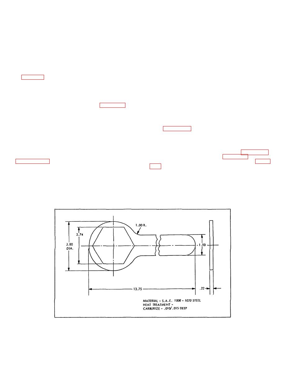
1. Loosen adjuster plug locknut (49, figure 4-32)
(37) to gear case with nuts (40) and washers (41). (See
with adjuster plug locknut wrench (figure 6-10) or equal.
Make wrench locally, if necessary, using data on figure
4. Assemble preform packing (46) to parking brake
lever (45) and gear case. Connect brake rod (5) to
2. Remove adjuster plug assembly (47, 48, 50
parking brake lever.
through 57) with spanner wrench.
5. Assemble axle shaft and brake drum to gear
case (47). Press bearing cone and roller (28) on axle
shaft along with internal
Figure 6-10. Steering Gear Adjuster Plug Locknut Wrench Details
6-17
|
|
Privacy Statement - Press Release - Copyright Information. - Contact Us |