 |
|||
|
|
|||
|
Page Title:
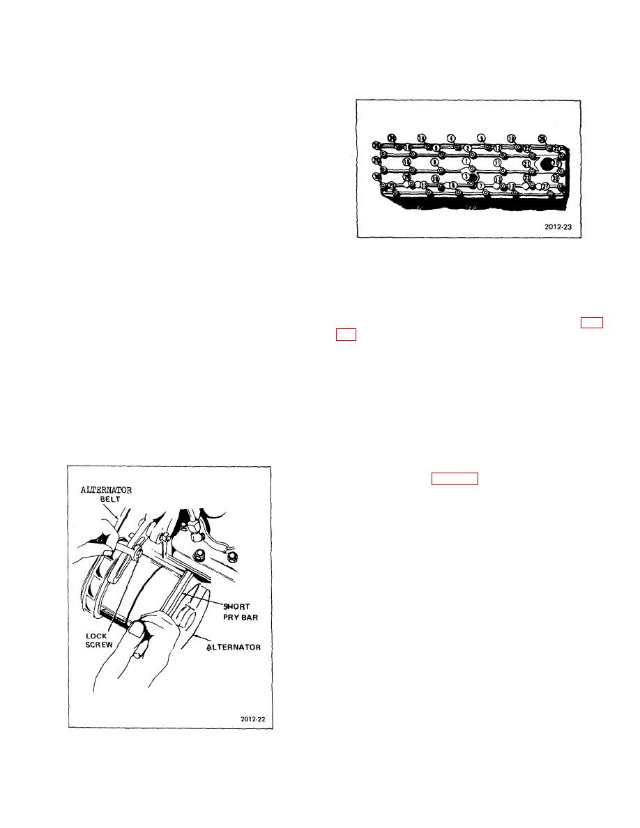
Figure 5-2. Cylinder Head Tightening Sequence |
|
||
| ||||||||||
|
|
 TM 10-3930-623-12
back raises the forks to the extreme top of the upright
assembly. Slowly push lever forward and allow the forks
to bottom by gravity. If, in raising the hoist, the lever is
not returned to neutral when top is reached, the overload
bypass in the control valve will open automatically and
detour the flow of oil back to the reservoir tank. This
action is indicated by a buzzing sound which is normal.
Note if there is any tendency for channels to bind and be
sure there is complete freedom of the crosshead
assembly, both up and down. In testing of the tilt
operation, when lever marked TILT is pulled back to its
extreme, the forks should tilt up and back. When the
TILT lever is pushed forward, the forks should tilt out and
down. Both tilting actions are accomplished by hydraulic
pressure. Note any tendency fox either the hoist or tilt
action to hesitate or mush.
Figure 5-2. Cylinder Head Tightening Sequence
5-7.
WEEKLY INSPECTION.
Perform the daily
2. Check fan belt tension. At firm thumb pressure
inspection. In addition:
at center of the long span, belt should yield 3/4-inch
minimum and one-inch maximum. Adjust tension as
1. Remove the pleated paper air cleaner element.
necessary by repositioning IDLER BELT TENSION (Fig.
Clean it by tapping it lightly on floor, then carefully
blowing surface dust from the exterior with compressed
air.
3. Check lubrication requirements (refer to LO
10-3930-623-12 )
CAUTION
5-8.
QUARTERLY PREVENTIVE MAINTENANCE
Do not blow high pressure airstream
SERVICES. Before this inspection, clean the truck,
at close range to the element. Do not
including the engine, transmission, drive and steering
wet the element for cleaning or any
axles and hoist mechanism, Use a steam cleaner or an
other reason.
approved type engine cleaning solution. After cleaning,
relubricate exposed parts of hoisting mechanism in
accordance with instructions LO 10-3930-623-12:
inspect according to table 5-3 and as follows:
1. Perform eight hour visual
and
operational
inspections, and weekly inspection.
2. Inspect all grease-fitting lubricated parts for
signs of wear.
3. Remove and inspect engine spark plugs. Clean
or replace, if necessary. Inspect condition of all ignition
wiring.
4. Remove distributor cap (but not wiring to cap).
Inspect interior for dirt accumulation or burned lines on
plastic surface.
5. Inspect distributor point gap, and condition of
points. If points are serviced (adjusted, cleaned, or
replaced), check ignition timing with a timing light.
5-9. ENGINE MAINTENANCE.
Figure 5-1. Tensioning Alternator Belt
5-2
|
|
Privacy Statement - Press Release - Copyright Information. - Contact Us |
