 |
|||
|
|
|||
|
|
|||
| ||||||||||
|
|
 (3) Loosen locknut on speed adjust screw and
(2) Remove clip at carburetor end of throttle
adjust screw down to increase governed speed, and up
rod and remove throttle rod.
to decrease speed.
b. Throttle linkage installation. Reverse a. above.
(4) Tighten locknut to retain governor setting.
If engine speed surges at governed speed, loosen
c. Adjustment.
locknut on surge adjust screw and turn screw in until
surging ceases.
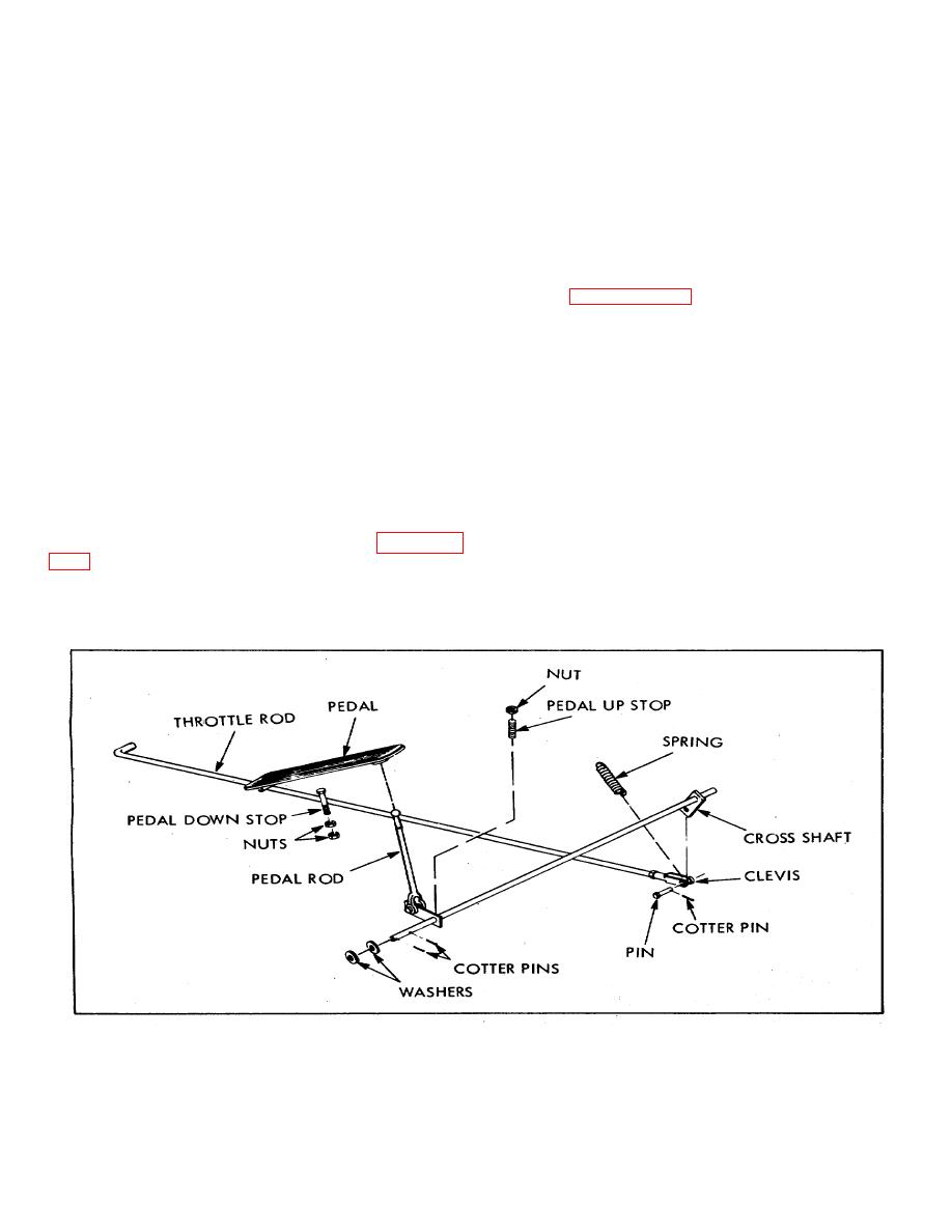
(1) With linkage installed, depress pedal by
hand until carburetor throttle is fully open. Adjust pedal
b. Removal.
down stop to contact under surface of pedal at this point.
(1) Remove radiator.
(2) With carburetor idle speed and mixture
adjusted (paragraph 6-68a.) and spring holding pedal
(2) Remove nuts and lockwashers from both
and linkage at idle position, adjust pedal up stop to
ends of rod to governor and remove linkage.
contact arm of cross shaft.
(3) Remove capscrews from top and bottom
d. Choke linkage removal.
of governor mounting flange, and remove governor.
(1) Loosen screw holding choke wire to
c.
Installation.
Reverse procedures in b.
carburetor, and screw clamping choke cable.
above.
(2) Remove nut and washer from underside of
choke knob mounting and withdraw choke cable and
6-73.
THROTTLE AND CHOKE CONTROLS.
knob from truck.
a. Throttle linkage removal.
e. Choke linkage installation. Reverse d. above.
(1)
Pull toe end of pedal (Figure 6-
f. Adjustment.
Loosen choke wire screw at
carburetor, open choke valve fully by hand, press choke
at both ends. Remove cotter pins at each end of cross
knob fully down, and tighten choke wire screw.
shaft, outer two washers, cotter pin and clevis pin at
front of throttle rod, and remove cross shaft and pedal
rod.
Figure 6-27. Carburetor Linkages
98
|
|
Privacy Statement - Press Release - Copyright Information. - Contact Us |
